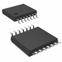
LM2743MTCX/NOPB National Semiconductor, LM2743MTCX/NOPB Datasheet - Page 11

LM2743MTCX/NOPB
Manufacturer Part Number
LM2743MTCX/NOPB
Description
IC REG CTLR BUCK N-CH 14-TSSOP
Manufacturer
National Semiconductor
Series
PowerWise®r
Type
Step-Down (Buck)r
Datasheet
1.LM2743MTCNOPB.pdf
(26 pages)
Specifications of LM2743MTCX/NOPB
Internal Switch(s)
No
Synchronous Rectifier
Yes
Number Of Outputs
1
Voltage - Output
0.6 ~ 13.5 V
Current - Output
20A
Frequency - Switching
50kHz ~ 1MHz
Voltage - Input
1 ~ 16 V
Operating Temperature
-40°C ~ 125°C
Mounting Type
Surface Mount
Package / Case
14-TSSOP
For Use With
LM2743EVAL - BOARD EVALUATION LM2743LM2743-19AEVAL - BOARD EVALUATION LM2743-19A
Lead Free Status / RoHS Status
Lead free / RoHS Compliant
Power - Output
-
Other names
LM2743MTCX
Available stocks
Company
Part Number
Manufacturer
Quantity
Price
Company:
Part Number:
LM2743MTCX/NOPB
Manufacturer:
UNITRODE
Quantity:
6 218
Part Number:
LM2743MTCX/NOPB
Manufacturer:
TI/德州仪器
Quantity:
20 000
TRACKING A VOLTAGE SLEW RATE
The tracking feature can alternatively be used not to make
both rails reach regulation at the same time but rather to have
similar rise rates (in terms of output dV/dt). This method en-
sures that the output voltage of the LM2743 always reaches
regulation before the output voltage of the master supply. Be-
cause the output of the master supply is divided down, in order
to track properly the output voltage of the LM2743 must be
lower than the voltage of the master supply. In this case, the
tracking resistors can be determined based on the following
equation:
For the example case of V
R
equation to be 265Ω. A timing diagram for the case of equal
slew rates is shown in
SEQUENCING
The start up/soft-start of the LM2743 can be delayed for the
purpose of sequencing by connecting a resistor divider from
the output of a master power supply to the SD pin, as shown
in
T1
Figure
set to 150Ω as before, R
FIGURE 2. Tracking with Equal Soft-Start Time
FIGURE 3. Tracking with Equal Slew Rates
4.
Figure
OUT1
T2
3.
= 5V and V
is calculated from the above
OUT2
= 1.8V, with
20095208
20095210
11
A desired delay time t
supply output voltage and the LM2743 output voltage can be
set based on the SD pin low-to-high threshold V
slew rate of the voltage at the SD pin, SR
Note again, that in
been represented symbolically as V
showing the power components.
V
pin voltage. The values of the sequencing divider resistors
R
voltage slew rate, SR
For example, if the master supply output voltage slew rate
was 1V/ms and the desired delay time between the startup of
the master supply and LM2743 output voltage was 5ms, then
the desired SD pin slew rate would be (1.08V/5 ms) = 0.216V/
ms. Due to the internal impedance of the SD pin, the maxi-
mum recommended value for R
desired slew rate, R
for this example is shown in
SD-IH
S1
and R
is typically 1.08V and SR
S2
set the SR
FIGURE 4. Sequencing Circuit
Figure
t
S1
DELAY
DELAY
OUT1
would then be 274Ω. A timing diagram
SD
4, the LM2743’s output voltage has
, using the following equation:
= V
based on the master supply output
between the startup of the master
Figure
SD-IH
SD
S2
/ SR
is the slew rate of the SD
OUT2
5.
is 1kΩ. To achieve the
SD
, i.e. without explicitly
SD
:
SD-IH
www.national.com
20095214
and the


