LM2743MTCX/NOPB National Semiconductor, LM2743MTCX/NOPB Datasheet - Page 17

LM2743MTCX/NOPB
Manufacturer Part Number
LM2743MTCX/NOPB
Description
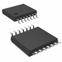
IC REG CTLR BUCK N-CH 14-TSSOP
Manufacturer
National Semiconductor
Series
PowerWise®r
Type
Step-Down (Buck)r
Datasheet
1.LM2743MTCNOPB.pdf
(26 pages)
Specifications of LM2743MTCX/NOPB
Internal Switch(s)
No
Synchronous Rectifier
Yes
Number Of Outputs
1
Voltage - Output
0.6 ~ 13.5 V
Current - Output
20A
Frequency - Switching
50kHz ~ 1MHz
Voltage - Input
1 ~ 16 V
Operating Temperature
-40°C ~ 125°C
Mounting Type
Surface Mount
Package / Case
14-TSSOP
For Use With
LM2743EVAL - BOARD EVALUATION LM2743LM2743-19AEVAL - BOARD EVALUATION LM2743-19A
Lead Free Status / RoHS Status
Lead free / RoHS Compliant
Power - Output
-
Other names
LM2743MTCX
Available stocks
Company
Part Number
Manufacturer
Quantity
Price
Company:
Part Number:
LM2743MTCX/NOPB
Manufacturer:
UNITRODE
Quantity:
6 218
Part Number:
LM2743MTCX/NOPB
Manufacturer:
TI/德州仪器
Quantity:
20 000
One popular method for selecting the compensation compo-
nents is to create Bode plots of gain and phase for the power
stage and error amplifier. Combined, they make the overall
bandwidth and phase margin of the regulator easy to see.
Software tools such as Excel, MathCAD, and Matlab are use-
ful for showing how changes in compensation or the power
stage affect system gain and phase.
The power stage modulator provides a DC gain A
equal to the input voltage divided by the peak-to-peak value
of the PWM ramp. This ramp is 1.0VP-P for the LM2743. The
inductor and output capacitor create a double pole at fre-
quency f
single zero at frequency f
3.3V, these quantities are:
In the equation for f
sistance, and represents the inductor DCR plus the on resis-
tance of the top power MOSFET. R
divided by output current. The power stage transfer function
G
Bode plots of the phase and gain in this example.
PS
a = LC
is given by the following equation, and
DP
FIGURE 13. Power Stage and Error Amp
O
(R
, and the capacitor ESR and capacitance create a
O
+ R
C
)
DP
, the variable R
ESR
. For this example, with V
L
O
is the power stage re-
is the output voltage
Figure 14
DC
20095264
shows
that is
IN
=
17
The double pole at 4.5 kHz causes the phase to drop to ap-
proximately -130° at around 10 kHz. The ESR zero, at 20.3
kHz, provides a +90° boost that prevents the phase from
dropping to -180º. If this loop were left uncompensated, the
bandwidth would be approximately 10 kHz and the phase
margin 53°. In theory, the loop would be stable, but would
suffer from poor DC regulation (due to the low DC gain) and
would be slow to respond to load transients (due to the low
bandwidth.) In practice, the loop could easily become unsta-
ble due to tolerances in the output inductor, capacitor, or
changes in output current, or input voltage. Therefore, the
loop is compensated using the error amplifier and a few pas-
sive components.
For this example, a Type III, or three-pole-two-zero approach
gives optimal bandwidth and phase.
In most voltage mode compensation schemes, including
Type III, a single pole is placed at the origin to boost DC gain
as high as possible. Two zeroes f
double pole frequency to cancel the double pole phase lag.
Then, a pole, f
A final pole f
The gain of the error amplifier transfer function is selected to
give the best bandwidth possible without violating the Nyquist
stability criteria. In practice, a good crossover point is one-fifth
b = L + C
c = R
O
FIGURE 14. Power Stage Gain and Phase
+ R
O
P2
(R
L
is placed at one-half of the switching frequency.
P1
O
R
is placed at the frequency of the ESR zero.
L
+ R
O
R
C
+ R
C
R
Z1
L
)
and f
Z2
are placed at the
20095269
20095270
www.national.com


