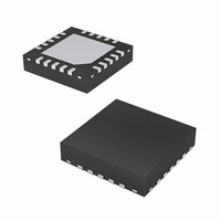
EL7520ILZ-T13 Intersil, EL7520ILZ-T13 Datasheet - Page 17

EL7520ILZ-T13
Manufacturer Part Number
EL7520ILZ-T13
Description
IC CTRLR DC/DC 4-CHAN 20-QFN
Manufacturer
Intersil
Type
Step-Up (Boost)r
Datasheet
1.EL7520AILZ-T13.pdf
(18 pages)
Specifications of EL7520ILZ-T13
Internal Switch(s)
No
Synchronous Rectifier
No
Number Of Outputs
4
Current - Output
40mA
Frequency - Switching
1MHz
Voltage - Input
3 ~ 5.5 V
Operating Temperature
-40°C ~ 85°C
Mounting Type
Surface Mount
Package / Case
20-VQFN Exposed Pad, 20-HVQFN, 20-SQFN, 20-DHVQFN
Lead Free Status / RoHS Status
Lead free / RoHS Compliant
Voltage - Output
-
Power - Output
-
Over-Temperature Protection
An internal temperature sensor continuously monitor the die
temperature. In the event that the die temperature exceeds
the thermal trip point, the device will shut down. The upper
and lower trigger points are typically set to 130°C and -90°C
respectively.
Layout Recommendation
The device's performance including efficiency, output noise,
transient response and control loop stability is dramatically
affected by the PCB layout. PCB layout is critical, especially
at high switching frequency.
There are some general guidelines for layout:
A demo board is available to illustrate the proper layout
implementation.
1. Place the external power components (the input
2. Place V
3. Reduce the loop with large AC amplitudes and fast slew
4. The feedback network should sense the output voltage
5. The power ground (PGND) and signal ground (SGND)
capacitors, output capacitors, boost inductor and output
diodes, etc.) in close proximity to the device. Traces to
these components should be kept as short and wide as
possible to minimize parasitic inductance and resistance.
rate.
directly from the point of load, and be as far away from LX
node as possible.
pins should be connected at only one point.
REF
and V
DD
bypass capacitors close to the pins.
17
EL7520, EL7520A
July 12, 2005
FN7318.0


