ISL65426HRZS2698 Intersil, ISL65426HRZS2698 Datasheet - Page 18
ISL65426HRZS2698
Manufacturer Part Number
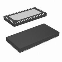
ISL65426HRZS2698
Description
IC REG DUAL SYNC BUCK 6A 50-QFN
Manufacturer
Intersil
Type
Step-Down (Buck)r
Datasheet
1.ISL65426HRZ.pdf
(22 pages)
Specifications of ISL65426HRZS2698
Internal Switch(s)
Yes
Synchronous Rectifier
Yes
Number Of Outputs
2
Voltage - Output
1 ~ 4 V
Current - Output
6A
Frequency - Switching
1MHz
Voltage - Input
3 ~ 5.5 V
Operating Temperature
-10°C ~ 100°C
Mounting Type
Surface Mount
Package / Case
50-VQFN
Lead Free Status / RoHS Status
Lead free / RoHS Compliant
Power - Output
-


load device. Individual power-good indicators provide
options for linking to external system monitors.
Undervoltage Protection
Separate hysteretic comparators monitor the feedback pin
(FB) of each converter channel. The feedback voltage is
compared to a set undervoltage (UV) threshold based on the
output voltage selected. Once one of the comparators trip
indicating a valid UV condition, a 4-bit UV counter
increments. If both channel comparators detect an UV
condition during the same switching cycle, the 4-bit counter
increments twice. Once the 4-bit counter overflows, the UV
protection logic shuts down both regulators.
The comparator is reset if the feedback voltage rises back
up above the UV threshold plus a specified amount of
hysteresis outlined in the “Electrical Specifications” table. If
both converter channels experience an UV condition and
one rises back within regulation, then the counter continues
to progress toward overflow.
Overvoltage Response
If the output voltage exceeds the overvoltage (OV) level for
the power-good signal, the controller will fight this condition
by actively trying to regulate the output voltage back down to
the reference level. This method of fighting the rise in output
voltage is limited by the reverse current capability of the total
number of power blocks associated with the output. The
approximate reverse current capability of each power block
is 0.5A. The power-good signal will drop indicating the
output voltage is out of specification. This signal will not
transition high again until the output voltage has dropped
below the falling PGOOD OV threshold.
Overcurrent Protection
A pilot device is integrated into the upper device structure of
each master power block. The pilot device samples current
through the master power block upper device each cycle. This
channel current feedback is scaled based on the state of the
ISET1 and ISET2 pins. The channel current information is
compared to an overcurrent (OC) limit based on the power
block configuration. Each 1A power block tied to the master
power block increases the OC limit by 2A. For example, if
both masters have two slaves associated with each of them
then the OC limit for each output is 6A for a 3A configuration.
If the sampled current exceeds the OC threshold, a 4-bit OC
up/down counter increments by one LSB. If the sampled
current falls below the OC threshold before the counter
overflows, the counter is reset. If both regulators experience
an OC event during the same cycle, the counter increments
twice. Once the OC counter reaches 1111, both channels are
shutdown. If both channels fall below the overcurrent limit
during the same cycle, the OC counter is reset.
Once in shutdown, the controller enters a delay interval,
equivalent to the SS interval, allowing the die to cool. The
OC counter is reset entering the delay interval. The
18
ISL65426
protection logic initiates a normal SS internal once the delay
interval ends. If the outputs both successfully soft-start, the
power-good signal goes high and normal operation
continues. If OC conditions continue to exist during the SS
interval, the OC counter must overflow before the controller
shutdowns both outputs again. This hiccup mode continues
indefinitely until both outputs soft-start successfully.
Note: It is recommended to add a Schottky diode of
adequate rating from LX1 to PGND and from LX5 to PGND
to avoid severe negative ringing that can disturb the OC
counter.
Thermal Monitor
Thermal-overload protection limits total power dissipation in
the ISL65426. An internal thermal sensor monitors die
temperature continuously. If controller junction temperature
exceeds +150
circuitry to shutdown both channels and latch-off. The POR
latch is reset by cycling VCC to the controller.
Component Selection Guide
This design guide is intended to provide a high-level
explanation of the steps necessary to create a power
converter. It is assumed that the reader is familiar with many
of the basic skills and techniques referenced in the following.
In addition to this guide, Intersil provides a complete
reference design that includes schematics, a bill of materials
and example board layout.
Output Filter Design
The output inductor and the output capacitor bank together
form a low-pass filter responsible for smoothing the pulsating
voltage at the phase node. The output filter also must
provide the transient energy until the regulator can respond.
Due to its inherent low bandwidth as compared to the
switching frequency, the output filter limits the system
transient response. The output capacitors must supply or
sink load current while the current in the output inductors
increases or decreases to meet the demand.
OUTPUT CAPACITOR SELECTION
The critical load parameters in choosing the output capacitors
are the maximum size of the load step (ΔI), the load-current
slew rate (di/dt), and the maximum allowable output voltage
deviation under transient loading (ΔV
characterized according to their capacitance, ESR (Equivalent
Series Resistance), and ESL (Equivalent Series Inductance).
At the beginning of the load transient, the output capacitors
supply all of the transient current. The output voltage will initially
deviate by an amount approximated by the voltage drop across
the ESL. As the load current increases, the voltage drop across
the ESR increases linearly until the load current reaches its final
value. Neglecting the contribution of inductor current and
°C
, the thermal monitor commands the POR
MAX
). Capacitors are
March 25, 2008
FN6340.3
Related parts for ISL65426HRZS2698
Image
Part Number
Description
Manufacturer
Datasheet
Request
R

Part Number:
Description:
Intersil Corporation [CMOS Serial Controller Interface]
Manufacturer:
Intersil Corporation
Datasheet:
Part Number:
Description:
Manufacturer:
Intersil Corporation
Datasheet:
Part Number:
Description:
357-036-542-201 CARDEDGE 36POS DL .156 BLK LOPRO
Manufacturer:
Intersil Corporation
Datasheet:
Part Number:
Description:
1024-Word x 4-Bit LSI Static RAM
Manufacturer:
Intersil Corporation
Datasheet:
Part Number:
Description:
General Purpose NPN Transistor Arrays FN341.4
Manufacturer:
Intersil Corporation
Datasheet:
Part Number:
Description:
CMOS 16-Bit Microprocessor
Manufacturer:
Intersil Corporation
Datasheet:
Part Number:
Description:
Manufacturer:
Intersil Corporation
Datasheet:
Part Number:
Description:
Manufacturer:
Intersil Corporation
Datasheet:
Part Number:
Description:
Manufacturer:
Intersil Corporation
Datasheet:
Part Number:
Description:
Manufacturer:
Intersil Corporation
Datasheet:
Part Number:
Description:
CMOS 6-Bit Latch and Decoder Memory Interfaces
Manufacturer:
Intersil Corporation
Datasheet:
Part Number:
Description:
CA3046General Purpose NPN Transistor Arrays
Manufacturer:
Intersil Corporation
Datasheet:
Part Number:
Description:
Manufacturer:
Intersil Corporation
Datasheet:
Part Number:
Description:
TR909 DLC/FLC SLIC with Low Power Standby
Manufacturer:
Intersil Corporation
Datasheet:
Part Number:
Description:
Manufacturer:
Intersil Corporation
Datasheet: