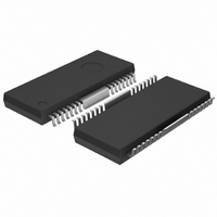
BA6665FM Rohm Semiconductor, BA6665FM Datasheet

BA6665FM
Specifications of BA6665FM
Available stocks
Related parts for BA6665FM
BA6665FM Summary of contents
Page 1
... Optical disc ICs Motor driver for CD-ROMs BA6665FM The BA6665FM is a CD-ROM spindle motor driver supporting reverse-rotation preventing circuit. It incorporates power save circuit, thermal shut down circuit, FG output, hall bias, etc. The 3-phasefall-wave pseudo linear driving system achieves high-performance and multi-function. ...
Page 2
... Optical disc ICs Block diagram FIN Hall Hall Hall 3 14 DRIVER TSD GAIN CONTROL REV CURRENT SENSE AMP PS TL TORQUE SENSE AMP Hall Bias VCC (Typ.) 1.6k VCC (Typ.) 1.6k VCC (Typ.) 1.6k FIN BA6665FM SERVO 22 SIGNAL ...
Page 3
... Torque control standard voltage input terminal Torque control voltage input terminal START / STOP switch 24 R Reverse terminal Power supply for signal division CC 26 N.C. N.C. V Power supply for driver 27 M Terminal connection for current sensing resistor FIN FIN GND Function BA6665FM ...
Page 4
... A 0.56 0.7 0. 4.5 4.9 5 0.25 0.4 V 1.0 1.5 V 0.4 0 560 700 840 mA 2.5 V 1.0 V BA6665FM =12V) M Conditions Test Circuit At power save ON Fig.1 At power save OFF Fig.1 Fig.2 Fig.2 I 10mA HB Fig.3 Fig.3 Fig.3 Fig 0.5V~3. 1.65V Fig 1.65V Fig 1.65V ...
Page 5
... VPSOFF : Range of 'VPS' that output pins VRSON : Range of 'VREV' that output pins VRSOFF : Range of 'VREV' that output pins ITL Test Circuit BA6665FM VPS=0 [V] H1 ~H3 =(1/2) VCC+0.1 [V] H1 ~H3 =(1/2) VCC [V] VPS=5 [V] H1 ~H3 =(1/2) VCC+0.1 [V] H1 ~H3 =(1/2) VCC [V] VPS=5 [V] IHB=10 [mA] become input-output table. (Input condition 1~6) become open. ...
Page 6
... Low 5pin 5pin Low 3pin HI 3pin Low IHA : Value of 'A1' (Hn =4.0V, Hn =2.5V) VHAR : Hall voltage range that output pins VINH : Hall input level that output pins Test Circuit BA6665FM Value of 'A2' (Hn =2.5V, Hn =4.0V) n= become input-output table. become input-output table =2.5V (n= ...
Page 7
... GEC={(V1 V2) / (1.5 1.3)} / RNF GEC={(V4 V3) / (2.0 1.8)} / RNF RNF=0 Test Circuit BA6665FM by input condition and IO= 600mA, value of 'VOH'. (VM-RNF short) by input condition and IO=600mA, value of 'VOL'. value of 'V' become 3mV. Value of 'V' at EC=1.5V V2 Value of 'V' at EC=1.8V V3 Value of 'V' at EC=2.0V V4 ...
Page 8
... PS VOLTAGE : V (V) PS Fig.8 PS Threshold voltage I (mA OFFSET VOLTAGE ; E E (mV Fig.11 Torque Control Offset voltage BA6665FM FG1 / FG2 / FG3 voltage change. (n= EC=ECR=1.65V Output open (Input condition 1~6) EC=5V, ECR=2.5V at IFG=3mA (Hn =L) at IFG (Hn = 100 HALL BIAS CURRENT : I VH Fig.9 Hall Bias voltage ...
Page 9
... O Fig.14 Output Saturation voltage Low External dimensions (Units : mm) 18.5 ± 0 5.15 ± 0.1 0.8 0.35 ± 0.1 0.3Min. HSOP-M28 OUTPUT CURRENT : I (A) O 1.0 2.0 1.0 2.0 1.0 2.0 Fig.13 Output Saturation voltage HI 0.15 BA6665FM 100 SUPPLY VOLTAGE : V ( Fig.15 Predrive Current ...


