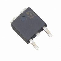
FLC10-200B STMicroelectronics, FLC10-200B Datasheet - Page 4

FLC10-200B
Manufacturer Part Number
FLC10-200B
Description
IC FIRE LIGHTER CIRCUIT D-PAK
Manufacturer
STMicroelectronics
Datasheet
1.FLC10-200H.pdf
(8 pages)
Specifications of FLC10-200B
Applications
*
Mounting Type
Surface Mount
Package / Case
DPak, TO-252 (2 leads+tab), SC-63
Lead Free Status / RoHS Status
Lead free / RoHS Compliant
Available stocks
Company
Part Number
Manufacturer
Quantity
Price
Company:
Part Number:
FLC10-200B
Manufacturer:
ST-MICROELECTRONICS
Quantity:
276
Rs
FLC10-200H/B
The maximum Rs value is equal to :
* : see fig 1
4/8
Fig. 2: BASIC APPLICATION
The applications of the lighter using the capaci-
tance discharge topology operate in 2 phases :
PHASE 1
The energy coming from the mains is stored into
the capacitor C. For that, the AC voltage is rectified
by the diode Ds.
COMPONENT CHOICE
RS RESISTOR CALCULATION
The Rs resistor allows, in addition with the capacitor C, the spark frequency to be adjusted and the cur-
rent from the mains to be limited. Its value shall allow the thyristor Th to fire even in worst case condi-
tions. In this borderline case, the system must fire with the lowest value of RMS mains voltage while
the breakdown voltage and current of the FLC are at the maximum.
MAINS
max
AC
(
V
AC
min.
Rs
2
)
[
V
BO
k I
max .(
.
Ds
BO
1
*
T T
.(
Z
R
amb
25
PHASE 2
At the end of the phase 1, the voltage across the
capacitor C reaches the avalanche threshold of
the zener. Then a current flows through the gate of
the thyristor Th which fires.
The firing of the thyristor causes an alternating
current to flow through the capacitor C.
The positive parts of this current flow through C,
Th and the primary of the HV transformer.
The negative parts of the current flow through C,
D and the primaty of the HV transformer.
Th
))]
D
c
Ic
Ic
t


