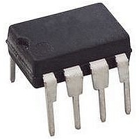
ACPL-312U-000E Avago Technologies US Inc., ACPL-312U-000E Datasheet

ACPL-312U-000E
Specifications of ACPL-312U-000E
Available stocks
Related parts for ACPL-312U-000E
ACPL-312U-000E Summary of contents
Page 1
... V/100 A. For IGBTs with higher ratings, the ACPL-312U series can be used to drive a discrete power stage which drives the IGBT gate. 2 Avago R Coupler isolation products provide the rein- forced insulation and reliability needed for critical in auto- motive and high temperature industrial applications. Functional Diagram ACPL-312U-000E ANODE 2 CATHODE 3 N/C 4 ...
Page 2
... Example 1: ACPL-312U-500E to order product of gullwing DIP-8 package in Tape and Reel packaging with RoHS compliant. Example 2: ACPL-312U-000E to order product of DIP-8 package in tube packaging with RoHS compliant. Option datasheets are available. Contact your Avago sales representative or authorized distributor for information. Package Outline Drawings ACPL-312U-000E Standard DIP Package 9.65 ± ...
Page 3
... NOTE: FLOATING LEAD PROTRUSION IS 0.25 mm (10 mils) MAX. Recommended Pb-Free IR Profile Recommended reflow condition as per JEDEC Standard, J-STD-020 (latest revision). Non-Halide Flux should be used. Regulatory Information The ACPL-312U-000E is approved by the following organizations: UL Recognized under UL 1577, component recognition program CSA Approved under CSA Component Acceptance Notice #5, File CA88324. ...
Page 4
... Creepage and clearance distances will also change depending on factors such as pollution degree and insulation level. [1] Symbol V IORM IOTM INPUT Ps ,OUTPUT R IO ACPL-312U Units I-IV I-IV I-III 55/125/21 2 630 V PEAK 1181 V PEAK 945 V PEAK 6000 V PEAK 175 °C ...
Page 5
Absolute Maximum Ratings Parameter Storage Temperature Operating Temperature Average Input Current Peak Transient Input Current (<1 μs pulse width, 300 pps) Reverse Input Voltage “High” Peak Output Current “Low” Peak Output Current Supply Voltage Input Current (Rise/Fall Time) Output Voltage ...
Page 6
DC Electrical Specifications Over recommended operating conditions (T = -40 to 125° mA F(ON) Parameter Symbol High Level Output Current I OH Low Level Output Current I OL High Level Output Voltage V ...
Page 7
... II-O ≤ 5 PA). 9. Device considered a two-terminal device: pins and 4 shorted together and pins and 8 shorted together. 10. The difference between t and t between any two ACPL-312U parts under the same test condition. PHL PLH 11. Pins 1 and 4 need to be connected to LED common. ...
Page 8
-100 mA OUT -40 - – TEMPERATURE – °C A ...
Page 9
2. for I F CCH for I F CCL 1.50 -40 - – TEMPERATURE ...
Page 10
° 200 DUTY CYCLE = 50 kHz 100 – SERIES LOAD RESISTANCE – Figure ...
Page 11
0.1 μ Figure 17. I test circuit 0.1 μ ...
Page 12
500 : + – 10 KHz 3 50% DUTY CYCLE 4 Figure 23 and t test circuit and waveforms. PLH PHL ...
Page 13
... V by using a DMOS transistor OL with 1 : (typical) on resistance in its pull down circuit. When the ACPL-312U is in the low state, the IGBT gate is shorted to the emitter Minimizing Rg and the lead inductance from the ACPL-312U to the IGBT gate and emitter (possibly by mounting the ACPL-312U on a ...
Page 14
... T = 228.96mW < 400mW (abs. max.) OK Therefore, the power dissipation absolute maximum rating has not been exceeded for the example – GATE RESISTANCE – Figure 27. Energy dissipated in the ACPL-312U for each IGBT switching cycle 442°C 126°C/W = 467°C 83°C/W * ...
Page 15
... Without a detector shield, the dominant cause of op- tocoupler CMR failure is capacitive coupling from the input side of the optocoupler, through the package, to the detector IC as shown in Figure 29. The ACPL-312U improves CMR performance by using a detector IC with an optically transparent Faraday shield, which diverts the capacitively coupled current away from the sensitive IC circuitry ...
Page 16
... V – < 12.0) the optocoupler UVLO UVLO output will go into the low state with a typical delay, UVLO Turn Off Delay, of 0.6 Ps. When the ACPL-312U output is in the low state and the supply voltage rises above the ACPL-312U V threshold (11.0 < V UVLO+ optocoupler output will go into the high state (assumes LED is “ ...
Page 17
Output Power Derating Curve 450 400 350 300 250 200 150 100 Figure 37. Thermal derating curve, dependence of safety limiting value with case temperature per IEC/EN/DIN EN 60747-5-5. For product information ...


