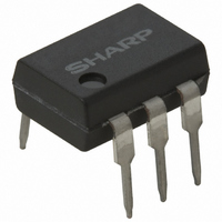
PC703V0YSZX Sharp Microelectronics, PC703V0YSZX Datasheet

PC703V0YSZX
Specifications of PC703V0YSZX
Related parts for PC703V0YSZX
PC703V0YSZX Summary of contents
Page 1
PC703VxNSZX Series/ PC703VxYSZX Series Features 1. TTL compatible output 2. High collector-emitter voltage (V :70V) CEO 3. Isolation voltage (Viso (rms):5kV) 4. Recognized by UL, file No.E64380 Approved by TÜV (VDE0884)(PC703VxYSZX Series) 5. 6-pin DIP package Applications 1. Home appliances ...
Page 2
... Classification table of collector current is shown below. *5 Model No. Rank mark PC703V1NSZX A B PC703V2NSZX PC703V3NSZX C D PC703V4NSZX PC703V5NSZX PC703V6NSZX PC703V7NSZX PC703V0NSZX Measuring Conditions I 10mA PC703V0YSZX Series are equivalent. Fig.1 Forward Current vs. Ambient Temperature Ambient temperature T PC703VxNSZX Series/PC703VxYSZX Series Symbol Conditions V I 20mA 0. =4V ...
Page 3
Fig.3 Peak Forward Current vs. Duty Ratio 10 000 5 000 2 000 1 000 500 200 100 Duty ratio Fig.5 Current Transfer Ratio vs. Forward Current ...
Page 4
Fig.9 Collector Dark Current vs. Ambient Temperature 20V Ambient temperature T Fig.11 Response Time vs. Load ...
Page 5
Application Circuits NOTICE The circuit application examples in this publication are provided to explain representative applications of SHARP devices and are not intended to guarantee any circuit design or license any intellectual property rights. SHARP takes no responsibility for any ...
Page 6
PC703VxNIZX Series Features 1. TTL compatible output 2. High collector-emitter voltage (V :70V) CEO 3. Isolation voltage (Viso (rms):5kV) 4. Recognized by UL, file No.E64380 5. 6-pin DIP package (Lead forming type) Applications 1. Home appliances 2. Programmable controllers 3. ...
Page 7
Electro-optical Characteristics Parameter Forward voltage Peak forward voltage Input Reverse current Terminal capacitance Output Collector dark current *4 Collector cullent Collector-emitter saturation voltage Isolation resistance Transfer charac- Floating capacitance teristics Cut-off frequency Rise time Response time Fall time *4 Classification ...
Page 8
Fig.3 Peak Forward Current vs. Duty Ratio 10 000 5 000 2 000 1 000 500 200 100 Duty ratio Fig.5 Current Transfer Ratio vs. Forward Current ...
Page 9
Fig.9 Collector Dark Current vs. Ambient Temperature 20V Ambient temperature T Fig.11 Response Time vs. Load ...
Page 10
Application Circuits NOTICE The circuit application examples in this publication are provided to explain representative applications of SHARP devices and are not intended to guarantee any circuit design or license any intellectual property rights. SHARP takes no responsibility for any ...


