KP-FSD2 Panduit Corp, KP-FSD2 Datasheet - Page 502
KP-FSD2
Manufacturer Part Number
KP-FSD2
Description
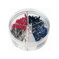
KIT FERRULE INS DIN AWG22-14
Manufacturer
Panduit Corp
Series
Pan-Term®r
Type
Ferrule Kitr
Datasheet
1.KP-FSD1.pdf
(1040 pages)
Specifications of KP-FSD2
Kit Type
Ferrule - Wire End
Values
400 pcs - Assorted Insulated 22 ~ 14 AWG Ferrules
Where Used
To terminate stranded wire for insertion into terminal blocks
Lead Free Status / Rohs Status
Lead free / RoHS Compliant


Management
Identification
Accessories
Connectors
Connectors
& Write-On
Protection
Grounding
Pre-Printed
Cable Ties
Terminals
Permanent
Solutions
Overview
Steel Ties
Lockout/
& Safety
Stainless
Raceway
Abrasion
Labeling
Systems
Markers
Tagout
System
Surface
Wiring
Power
Labels
Index
Cable
Cable
D1.30
Duct
E5.
B1.
B2.
B3.
C1.
C2.
C3.
C4.
D1.
D2.
D3.
E1.
E2.
E3.
E4.
A.
F.
Type P-FF
• Fork design provides for fast and easy installation, without the
• Flange design provides extra secure connection on a variety
• Internal barrel serrations assure good wire contact and maximum
Type P-LF
• Locks in place for secure connection
• Fork design provides for fast and easy installation, without the
• Internal barrel serrations assure good wire contact and maximum
• Brazed seam protects terminal barrel from splitting during the
need to remove fastener
of applications
tensile strength
need to remove fastener
tensile strength
crimp process
Order number of pieces required, in multiples of Standard Package Quantity.
C
C
L
L
Flanged Fork Terminal, Non-Insulated
Locking Fork Terminal, Non-Insulated
W
W
**Bulk packaging may be available, contact Panduit Customer Service for additional information.
‡UL and CSA approved tooling/product combinations. For crimping tool information, see pages D1.83, D1.84,
D1.86 and D1.88.
*Not UL Listed or CSA Certified.
**Bulk packaging may be available, contact Panduit Customer Service for additional information.
‡UL and CSA approved tooling/product combinations. For crimping tool information, see pages D1.83, D1.84,
D1.86 and D1.88.
Part Number
P18-8FF-C
P14-6FF-C
P14-8FF-C
P10-10FF-L
Part Number
P18-6LF-C
P18-6LFW-C
P18-8LF-C
P18-10LFN-C*
P18-10LF-C
P14-6LF-C
P14-6LFW-C
P14-8LF-C
P14-10LFN-C*
P14-10LF-C
P10-6LF-L
P10-8LF-L
P10-10LF-L
P10-14LF-L
ELECTRICAL SOLUTIONS
22 – 16 AWG
16 – 14 AWG
12 – 10 AWG
22 – 16 AWG
18 – 14 AWG
14 – 10 AWG
Range
Range
Wire
Wire
Thickness
Thickness
• Barrel of terminal internally beveled to provide quick and easy
• Maximum recommended operating temperature 302°F (150°C)
• UL and CSA rated up to 2000 V per UL 486A/B
Stock
Stock
• Brazed seam protects terminal barrel from splitting during the
• Barrel of terminal internally beveled to provide quick and easy
• Maximum recommended operating temperature 302°F (150°C)
• UL and CSA rated up to 2000 V per UL 486A/B
0.03
0.03
0.03
0.04
(In.)
(In.)
0.03
0.03
0.03
0.03
0.03
0.03
0.03
0.03
0.03
0.03
0.04
0.04
0.04
0.04
wire insertion
crimp process
wire insertion
Stud
Stud
Size
Size
#10
#10
#10
#10
#10
#10
1/4"
#8
#6
#8
#6
#6
#8
#6
#6
#8
#6
#8
0.72
0.65
0.72
0.80
0.68
0.70
0.74
0.74
0.74
0.70
0.70
0.77
0.77
0.77
0.77
0.79
0.79
0.92
Figure Dimensions
Figure Dimensions
L
L
(In.)
0.31
0.28
0.31
0.38
0.27
0.29
0.29
0.28
0.33
0.25
0.29
0.29
0.29
0.33
0.30
0.30
0.34
0.46
(In.)
W
W
0.25
0.22
0.25
0.28
0.22
0.22
0.23
0.23
0.23
0.22
0.22
0.27
0.27
0.27
0.23
0.23
0.23
0.33
C
C
Recommended
Recommended
Prime items appear in BOLD.
Installation
Installation
CT-600-A‡,
CT-600-A‡,
CT-600-A‡,
CT-600-A‡,
CT-600-A‡,
CT-100A‡,
CT-1570‡,
CT-100A‡,
CT-1570‡,
CT-1701‡,
CT-100A‡,
CT-1570‡,
CT-100A‡,
CT-1570‡,
CT-100A‡,
CT-1570‡,
CT-1701‡,
CT-2500‡
CT-2500‡
CT-2500‡
CT-2500‡
CT-2500‡
CT-200‡,
CT-200‡,
CT-200‡,
CT-200‡,
CT-200‡,
Tool
Tool
Qty.**
Qty.**
Pkg.
Pkg.
Std.
Std.
100
100
100
100
100
100
100
100
100
100
100
100
100
50
50
50
50
50
Std.
Ctn.
Qty.
Std.
Ctn.
Qty.
500
500
500
500
500
500
500
500
500
500
500
500
500
500
500
500
500
500