KP-FSD2 Panduit Corp, KP-FSD2 Datasheet - Page 760
KP-FSD2
Manufacturer Part Number
KP-FSD2
Description
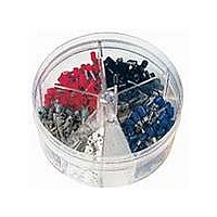
KIT FERRULE INS DIN AWG22-14
Manufacturer
Panduit Corp
Series
Pan-Term®r
Type
Ferrule Kitr
Datasheet
1.KP-FSD1.pdf
(1040 pages)
Specifications of KP-FSD2
Kit Type
Ferrule - Wire End
Values
400 pcs - Assorted Insulated 22 ~ 14 AWG Ferrules
Where Used
To terminate stranded wire for insertion into terminal blocks
Lead Free Status / Rohs Status
Lead free / RoHS Compliant


Management
Identification
Accessories
Connectors
Connectors
& Write-On
Protection
Grounding
Pre-Printed
Cable Ties
Terminals
Permanent
Solutions
Overview
Steel Ties
Lockout/
& Safety
D2.138
Stainless
Raceway
Abrasion
Labeling
Systems
Markers
Tagout
System
Surface
Wiring
Power
Labels
Index
Cable
Cable
Duct
E5.
B1.
B2.
B3.
C1.
C2.
C3.
C4.
D1.
D2.
D3.
E1.
E2.
E3.
E4.
A.
F.
For Use with Stranded Copper Code Conductors
Type CD
• Made from high strength electrolytic copper to provide premium
• Wide wire range-taking capability minimizes inventory
• Internal pressure bar and V-bottom collar provide uniform clamping
◆ CD400-38-3Y
◆ CD650-12-3Y
electrical and mechanical performance
requirements
force on conductor to assure positive contact between conductor
and connector
Part Number
CD35-36-QY
CD70-14-QY
CD125-14-QY
CD225-56-QY
CD300-38-3Y
**Uses slotted head set screw.
◆NEMA hole sizes and spacing.
Two-Hole, Straight Floating Tongue Lug
Copper Conductor Size Range
(1) #10 AWG with (1) #12 AWG,
(1) #12 AWG with (1) #14 AWG
(1) #8 AWG with (1) #4 AWG,
(1) #8 AWG with (1) #6 AWG
(2) #10 AWG, (2) #12 AWG,
600 kcmil – 1000 kcmil
#14 AWG – #6 AWG,
1/0 AWG – 500 kcmil
#12 AWG – #2 AWG
#1 AWG – 350 kcmil
#6 AWG – 4/0 AWG
#2 – 1/0 AWG
(2) #14 AWG,
Current
(Amps)
ELECTRICAL SOLUTIONS
Rating
125
225
300
400
650
50
90
Stud Hole
Size
3/16
5/16
(In.)
1/4
1/4
3/8
3/8
1/2
• Inspection window to visually assure full conductor insertion
• Plated steel set screw provides high strength, durable electrical
• cULus Listed and CSA Certified for use up to 600 V
• Available with NEMA hole sizes and spacing
H
Stud Hole
contact between conductor and connector
Spacing
1.00
1.00
1.00
1.00
1.00
1.75
1.75
(In.)
M
Hex Size
3/16
5/16
5/16
(In.)
3/8
**
**
**
L
SPACING
HOLE
P
2.13
2.26
2.94
3.38
4.94
5.62
6.88
L
T
W
0.38
0.50
0.62
1.00
1.00
1.50
2.00
W
Figure Dimensions
0.49
0.64
0.88
1.13
1.39
1.61
2.32
H
(In.)
Prime items appear in BOLD.
0.07
0.09
0.13
0.13
0.19
0.19
0.25
T
1.60
1.63
1.88
2.13
3.32
3.57
4.69
P
0.43
0.50
0.60
1.23
1.41
1.85
.94
M
Pkg.
Std.
Qty.
25
25
25
25
3
3
3