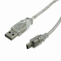
EXTMUSB3FT Matrix Orbital, EXTMUSB3FT Datasheet - Page 12

EXTMUSB3FT
Manufacturer Part Number
EXTMUSB3FT
Description
DISPLAY
Manufacturer
Matrix Orbital
Datasheet
1.EXTMUSB3FT.pdf
(21 pages)
Specifications of EXTMUSB3FT
Accessory Type
USB Cable
For Use With/related Products
GTT-480270A
Lead Free Status / RoHS Status
Lead free / RoHS Compliant
Other names
635-1045
4 Hardware
4.1 Standard Model
4.1.1
The Extended Communication/Power Header provides a standard connector for interfacing to the
GTT480272A. Voltage is applied through pins one and four of the header. Please ensure the correct
voltage input for your display by referencing the electrical specifications in Table 9 before applying
power. Pins two and three are reserved for serial transmission, using either RS-232/TTL communication
or clocking data through the I²C protocol, depending on what has been selected by the Protocol Select
Jumpers. Pins five and six are used for serial transmission hardware flow control, and ignored for I²C
communications. Please note that unlike older Matrix Orbital displays, hardware flow control is
mandatory for serial communications in RS232 or TTL modes. The Molex 22-04-1061 style header used
can be mated to a number of connectors.
4.1.2
Advanced applications may prefer the straight two by five pin connection offered through the optional
Alternate Serial Header. The Alternate Serial Header may be added to the GTT480272A for an added
charge as part of a custom order. Please use the Contact section to reach Sales for additional details.
4.1.3
The Protocol Select Jumpers provide the means necessary to alter the standard GTT480272A
communication setting between RS-232, TTL, and I²C. As a default, the jumpers are set to RS-232 mode
with solder jumps on the RS232 jumpers. In order to place the display module in I²C mode you must first
remove the solder jumps from the RS232 jumpers and then place them on the I
will now be in I²C mode and have a default slave address of 80, unless this address has been changed in
the AUTOEXEC start-up file. Similarly, in order to change the display to TTL mode, simply remove the
zero ohm resistors from the RS232 or I²C jumpers and solder them to the TTL jumpers.
Figure 7: Extended Communication/Power Header
Extended Communication/Power Header
Alternate Serial Header
Protocol Select Jumpers
Table 2: Extended Communication/Power Pinout
Pin
6
5
4
3
2
1
Function
Tx (SDA)
Rx (SCL)
2
RTS
CTS
Gnd
Vcc
C jumpers. The display
8


