HCMS-2919 Avago Technologies US Inc., HCMS-2919 Datasheet - Page 9
HCMS-2919
Manufacturer Part Number
HCMS-2919
Description
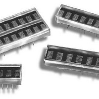
LED DISPLAY 5X7 8CHAR 3.8MM BLUE
Manufacturer
Avago Technologies US Inc.
Series
HCMS-29xxr
Datasheet
1.HCMS-2919.pdf
(14 pages)
Specifications of HCMS-2919
Display Type
Alphanumeric
Millicandela Rating
*
Size / Dimension
1.40" L x 0.40" W x 0.20" H (35.6mm x 10.2mm x 5.1mm)
Color
Blue
Configuration
5 x 7
Voltage - Forward (vf) Typ
*
Package / Case
26-DIP
Number Of Digits/alpha
8
Digit/alpha Size
0.15" (3.8mm)
Number Of Digits
8
Illumination Color
Blue
Wavelength
428 nm
Operating Voltage
5.5 V
Maximum Operating Temperature
+ 85 C
Minimum Operating Temperature
- 40 C
Luminous Intensity
170 ucd
Lead Free Status / RoHS Status
Lead free / RoHS Compliant
Common Pin
-
Lead Free Status / Rohs Status
Details


Control Register Data Loading
Data is loaded into the Control Register, MSB first,
according to the procedure shown in Table 1 and
Figure 3. First, RS is brought to logic high and then CE
is brought to logic low. Next, each successive rising
CLK edge will shift in the data on the DIN pin. Finally,
when 8 bits have been loaded, the CE line is brought
to logic high. When CLK goes to logic low, new data is
copied into the selected control word. Loading data
into the Control Register takes place while the previous
control word configures the displays.
Control Word 0
Loading the Control Register with D
selects Control Word 0 (see Table 2). Bits D
Table 2. Control Shift Register
9
Set Low
Set High
to Select
to Select
Control
Word 0
Control
Word 1
Bit D
Bit D
↑
H
↑
L
SLEEP MODE
7
7
D
L
6
Peak Current
Reserved for Future
Brightness
D
L
must be set Low)
Control
Use (Bits D
5
H
H
L
L
H
L
H
L
L - DISABLES INTERNAL OSCILLATOR-DISPLAY BLANK
H - NORMAL OPERATION
D
L
CONTROL WORD 0
CONTROL WORD 1
4
2
-D
6
L
D
H
H
H
H
H
H
H
H
Pixel Current
L
L
L
L
L
L
L
L
3
Typical Peak
PWM Brightness
(mA)
12.8
4.0
6.4
9.3
L
D
Control
H
H
L
H
H
H
H
L
H
H
L
L
L
L
L
L
7
2
- = Logic Low
0
D
D
-D
H
H
H
L
H
H
H
H
H
L
L
L
L
L
L
L
1
1
3
(Relative Brightness, %)
adjust
D
D
H
L
L
H
H
H
H
H
H
H
L
L
L
L
L
L
External Display Oscillator Prescaler
0
0
Scale Current
Relative Full
L - Oscillator Freq ÷ 1
H - Oscillator Freq ÷ 8
100
31
50
73 (Default at Power Up)
Serial/Simultaneous Data Out
the display brightness by pulse width modulating the
LED on time, while Bits D
brightness by changing the peak pixel current. Bit D
selects normal operation or sleep mode.
Sleep mode (Control Word 0, bit D
the Internal Display Oscillator and the LED pixel drivers.
This mode is used when the IC needs to be powered
up, but does not need to be active. Current draw in
sleep mode is nearly zero. Data in the Dot Register
and Control Words are retained during sleep mode.
Control Word 1
Loading the Control Register with D
selects Control Word 1. This control Word performs
two functions: serial/simultaneous data out mode and
external oscillator prescale select (see Table 2).
Oscillator
On-Time
L - D
H - D
Cycles
11
14
18
22
28
36
48
60
0
1
2
3
4
5
7
9
out
out
holds contents of Bit D
is functionally tied to D
Factor
Duty
11.7
(%)
0.2
0.4
0.6
0.8
1.0
1.4
1.8
2.1
2.7
3.5
4.3
5.5
7.0
9.4
0
Brightness
Relative
11.7
(%)
100
1.7
3.3
5.0
6.7
8.3
15
18
23
30
37
47
60
80
0
7
in
4
-D
5
adjusts the display
6
= Low) turns off
7
= Logic High
6
Related parts for HCMS-2919
Image
Part Number
Description
Manufacturer
Datasheet
Request
R

Part Number:
Description:
LED DISPLAY 5X7 4CHAR 5MM GREEN
Manufacturer:
Avago Technologies US Inc.
Datasheet:

Part Number:
Description:
LED DISPLAY 5X7 8CHAR 3.8MM YLW
Manufacturer:
Avago Technologies US Inc.
Datasheet:

Part Number:
Description:
LED DISPLAY 5X7 4CHAR 3.8MM YLW
Manufacturer:
Avago Technologies US Inc.
Datasheet:

Part Number:
Description:
LED DISPLAY 5X7 4CHAR 3.8MM ORN
Manufacturer:
Avago Technologies US Inc.
Datasheet:

Part Number:
Description:
LED DISPL 5X7 4CHAR 3.8MM ALGAAS
Manufacturer:
Avago Technologies US Inc.
Datasheet:
Part Number:
Description:
LED DISPLAY 5X7 4CHAR 3.8MM RED
Manufacturer:
Avago Technologies US Inc.
Datasheet:
Part Number:
Description:
LED DISPLAY 5X7 4CHAR 3.8MM ORN
Manufacturer:
Avago Technologies US Inc.
Datasheet:
Part Number:
Description:
LED DISPLAY 5X7 4CHAR 3.8MM YLW
Manufacturer:
Avago Technologies US Inc.
Datasheet:
Part Number:
Description:
LED DISPLAY 5X7 4CHAR 5MM YLW
Manufacturer:
Avago Technologies US Inc.
Datasheet:
Part Number:
Description:
LED DISPLAY 5X7 4CHAR 5MM ORN
Manufacturer:
Avago Technologies US Inc.
Datasheet:
Part Number:
Description:
LED DISPLAY 5X7 4CHAR 5MM GRN
Manufacturer:
Avago Technologies US Inc.
Datasheet:
Part Number:
Description:
LED DISPLAY 5X7 4CHAR 5MM RED
Manufacturer:
Avago Technologies US Inc.
Datasheet:
Part Number:
Description:
LED DISPLAY 5X7 4CHAR 3.8MM RED
Manufacturer:
Avago Technologies US Inc.
Datasheet:
Part Number:
Description:
LED DISPLAY 5X7 4CHAR 3.8MM GRN
Manufacturer:
Avago Technologies US Inc.
Datasheet:
Part Number:
Description:
LED DISPLAY 5X7 4CHAR 5MM GRN
Manufacturer:
Avago Technologies US Inc.
Datasheet: