M0240SD-402MDAR1-3 Newhaven Display, M0240SD-402MDAR1-3 Datasheet - Page 14
M0240SD-402MDAR1-3
Manufacturer Part Number
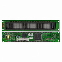
M0240SD-402MDAR1-3
Description
MODULE VF CHAR 2X40 5.34MM
Manufacturer
Newhaven Display
Datasheet
1.M0240SD-402MDAR1-3.pdf
(21 pages)
Specifications of M0240SD-402MDAR1-3
Outline L X W X H
182.00mm x 33.50mm x 17.60mm
Viewing Area
134.75mm L x 11.50mm W
Display Format
40 x 2
Display Type
Character
Format
5 x 8 Dots
Voltage - Supply
4.5 V ~ 5.5 V
Character Size
5.34mm H x 2.10mm W
Interface
Parallel
Operating Temperature
-20°C ~ 70°C
Product
Character Display Modules
Character Count X Line
40 x 2
Module Size (w X H X T)
182 mm x 33.5 mm x 17.6 mm
Voltage Rating
4.5 V to 5.5 V
Operating Temperature Range
- 20 C to + 70 C
Dot Format
5 x 8
Viewing Area (w X H)
134.75 mm x 11.5 mm
Lead Free Status / RoHS Status
Lead free / RoHS Compliant
Number Of Dots
-
Lead Free Status / Rohs Status
Details


STANDARD
NAME
Note Be sure the controller is not in the busy state (BF=0) before sending an instruction from the MPU to the
6.1 Outline
Only the instruction register (IR) and data register (DR) of the VFD controller can be controlled by the
user's MPU. Before starting the internal operation of the controller, control information is temporarily
stored into these registers to allow interfacing with various MPUs, which operate at different speeds, or
various peripheral control devices. The internal operation of the controller is determined by signals sent
from the MPU. These signals, which include register selection signal (RS), read/write signal (R/W), and
the data bus (DB0 to DB7), make up the controller instructions (See Table-13). There are four categories
of instructions that:
Normally instructions that perform data transfer with interval RAM are used the most.
However, auto-increment by 1 (or auto-decrement by 1) of internal RAM addresses after each data write
can lighten the program load of the MPU. Since the display shift instruction can perform concurrently
with display data write, the user can minimize system development time with maximum programming
efficiency
When an instruction is being executed for internal operation, no instruction other than the busy
flag/address read instruction can be executed. Because the busy flag is set to 1 while an instruction is
being executed, check it to make sure it is 0 before sending another instruction from the MPU.
nodule. If an instruction is sent without checking the busy flag, the time between the first instruction
and next instruction will take much longer than the instruction time itself.
Refer to Table-13 for the list of each instruction execution time.
designate controller functions, such as display format, data length, ect.
Set internal RAM addresses
Perform data transfer with internal RAM
Perform miscellaneous functions
DOCUMENT NO.
REV.NO
00
13/20
PAGE
Related parts for M0240SD-402MDAR1-3
Image
Part Number
Description
Manufacturer
Datasheet
Request
R

Part Number:
Description:
DISPLAY VFD ALPHA 1X20 6.5MM
Manufacturer:
Newhaven Display
Datasheet:

Part Number:
Description:
DISPLAY VFD ALPHA 1X16 5MM
Manufacturer:
Newhaven Display
Datasheet:

Part Number:
Description:
DISPLAY VFD 7-SEG 1X9 9.7MM
Manufacturer:
Newhaven Display
Datasheet:

Part Number:
Description:
DISPLAY VFD 7-SEG 1X6 20MM
Manufacturer:
Newhaven Display
Datasheet:

Part Number:
Description:
DISPLAY VFD 7-SEG 1X19 11MM
Manufacturer:
Newhaven Display
Datasheet:

Part Number:
Description:
DISPLAY VFD 7-SEG 1X3 8MM
Manufacturer:
Newhaven Display
Datasheet:

Part Number:
Description:
DISPLAY VFD CUSTOM DVD
Manufacturer:
Newhaven Display
Datasheet:

Part Number:
Description:
DISPLAY VFD CUST AUDIO
Manufacturer:
Newhaven Display
Datasheet:

Part Number:
Description:
DISPLAY VFD CUST AUDIO
Manufacturer:
Newhaven Display
Datasheet:

Part Number:
Description:
DISPLAY VFD 7-SEG 1X5 7.6MM
Manufacturer:
Newhaven Display
Datasheet:

Part Number:
Description:
DISPLAY VFD CUST APPLIANCE
Manufacturer:
Newhaven Display
Datasheet:

Part Number:
Description:
DISPLAY VFD CUSTOM DVD
Manufacturer:
Newhaven Display
Datasheet:

Part Number:
Description:
DISPLAY VFD 7-SEG 1X4 7.6MM
Manufacturer:
Newhaven Display
Datasheet:

Part Number:
Description:
DISPLAY VFD 7-SEG 1X9 8MM
Manufacturer:
Newhaven Display
Datasheet:

Part Number:
Description:
DISPLAY VFD 7-SEG 1X7 12.5MM
Manufacturer:
Newhaven Display
Datasheet: