M0240SD-402MDAR1-3 Newhaven Display, M0240SD-402MDAR1-3 Datasheet - Page 21
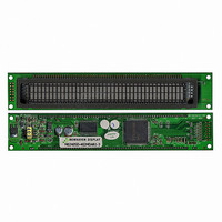
M0240SD-402MDAR1-3
Manufacturer Part Number
M0240SD-402MDAR1-3
Description
MODULE VF CHAR 2X40 5.34MM
Manufacturer
Newhaven Display
Datasheet
1.M0240SD-402MDAR1-3.pdf
(21 pages)
Specifications of M0240SD-402MDAR1-3
Outline L X W X H
182.00mm x 33.50mm x 17.60mm
Viewing Area
134.75mm L x 11.50mm W
Display Format
40 x 2
Display Type
Character
Format
5 x 8 Dots
Voltage - Supply
4.5 V ~ 5.5 V
Character Size
5.34mm H x 2.10mm W
Interface
Parallel
Operating Temperature
-20°C ~ 70°C
Product
Character Display Modules
Character Count X Line
40 x 2
Module Size (w X H X T)
182 mm x 33.5 mm x 17.6 mm
Voltage Rating
4.5 V to 5.5 V
Operating Temperature Range
- 20 C to + 70 C
Dot Format
5 x 8
Viewing Area (w X H)
134.75 mm x 11.5 mm
Lead Free Status / RoHS Status
Lead free / RoHS Compliant
Number Of Dots
-
Lead Free Status / Rohs Status
Details


STANDARD
NAME
7. 0
Note: The address counter (ACC) is automatically incremented or decremented by 1 after the write
7.1 Avoid applying excessive shock or vibration beyond the specification for the VFD module.
7.2 Since VFDs are made of glass material, careful handling is required.
7.6 Exceeding any of maximum ratings may cause the permanent damage.
7.7 Since the VFD modules contain high voltage source, careful handing is required during
7.8 When the power is turned off, the capacitor dose not discharge immediately.
7.9 The power supply must be capable of providing at least 3 times the rated current, because the
7.10 Avoid using the module where excessive noise interference is expected. Noise may affects the
7.11 Since all VFD modules contain C-MOS ICs, anti-static handing procedures are always required.
7.3 When mounting the VFD module to your system, leave a slight gap between the VFD glass and
7.5 Slow starting power supply may cause non-operation because one chip Micro won’t be reset.
7.4 Avoid plugging or unplugging the interface connection with the power on, otherwise it may cause
PERATING RECOMMENDATIONS
instructions to CG-RAM or DD-RAM are executed. The RAM data selected by the ACC cannot
be read out at this time even if read instructions are executed. Therefore, to correctly read data,
execute either the address set instruction or cursor shift instruction (only with DD-RAM), then
just before reading the desired data, execute the read instruction from the second time the read
instruction is sent.
interface cable less than 50cm.
your front panel. The module should be mounted without stress to avoid flexing of the PCB.
Interface signal and causes improper operation. And it is important to keep the length of the
i.e. Direct impact with hard material to the glass surface (especially exhaust tip) may crack the
glass.
powered on.
The high voltage applied to the VFD must not contact to the ICs. And the short-circuit
of mounted components on PCB within 30 times the specified current consumption when the
power is turned on.
surge current can be more than 3 times the specified current consumption when the power is
turned on.
the severe damage to input circuitry.
DOCUMENT NO.
REV.NO
00
20/20
PAGE
Related parts for M0240SD-402MDAR1-3
Image
Part Number
Description
Manufacturer
Datasheet
Request
R

Part Number:
Description:
DISPLAY VFD ALPHA 1X20 6.5MM
Manufacturer:
Newhaven Display
Datasheet:

Part Number:
Description:
DISPLAY VFD ALPHA 1X16 5MM
Manufacturer:
Newhaven Display
Datasheet:

Part Number:
Description:
DISPLAY VFD 7-SEG 1X9 9.7MM
Manufacturer:
Newhaven Display
Datasheet:

Part Number:
Description:
DISPLAY VFD 7-SEG 1X6 20MM
Manufacturer:
Newhaven Display
Datasheet:

Part Number:
Description:
DISPLAY VFD 7-SEG 1X19 11MM
Manufacturer:
Newhaven Display
Datasheet:

Part Number:
Description:
DISPLAY VFD 7-SEG 1X3 8MM
Manufacturer:
Newhaven Display
Datasheet:

Part Number:
Description:
DISPLAY VFD CUSTOM DVD
Manufacturer:
Newhaven Display
Datasheet:

Part Number:
Description:
DISPLAY VFD CUST AUDIO
Manufacturer:
Newhaven Display
Datasheet:

Part Number:
Description:
DISPLAY VFD CUST AUDIO
Manufacturer:
Newhaven Display
Datasheet:

Part Number:
Description:
DISPLAY VFD 7-SEG 1X5 7.6MM
Manufacturer:
Newhaven Display
Datasheet:

Part Number:
Description:
DISPLAY VFD CUST APPLIANCE
Manufacturer:
Newhaven Display
Datasheet:

Part Number:
Description:
DISPLAY VFD CUSTOM DVD
Manufacturer:
Newhaven Display
Datasheet:

Part Number:
Description:
DISPLAY VFD 7-SEG 1X4 7.6MM
Manufacturer:
Newhaven Display
Datasheet:

Part Number:
Description:
DISPLAY VFD 7-SEG 1X9 8MM
Manufacturer:
Newhaven Display
Datasheet:

Part Number:
Description:
DISPLAY VFD 7-SEG 1X7 12.5MM
Manufacturer:
Newhaven Display
Datasheet: