AFBR-5905Z Avago Technologies US Inc., AFBR-5905Z Datasheet
AFBR-5905Z
Specifications of AFBR-5905Z


Related parts for AFBR-5905Z


AFBR-5905Z Summary of contents
Page 1
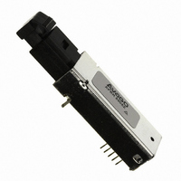
... DIP style with ATM 2 km Backbone Links a MT-RJ fiber connector The AFBR-5905Z is a 1300 nm product with optical perfor- interface. mance compliant with the SONET STS-3c (OC-3) Physical ATM 2 km Backbone Links Layer Interface Specification. This physical layer is defined ...
Page 2
... Receiver Sections The receiver section of the AFBR-5905Z utilizes an InGaAs PIN photodiode coupled to a custom silicon transimped- ance preamplifier IC packaged in the optical sub- are squelched at Signal Detect assembly portion of the receiver. This PIN/preamplifier Deassert. That is, when the combination is coupled to a custom quantizer IC which ...
Page 3
OVERALL RECEPTACLE CENTER LINE) Case temperature measurement point 13.59 9.6 (0.378) (0.535) MAX. MAX. 12 (0.472) 9.3 9.8 (0.366) (0.386) MAX. MAX. Ø 1.07 (0.042) DIMENSIONS IN MILLIMETERS (INCHES) NOTES: 1. THIS PAGE DESCRIBES THE MAXIMUM ...
Page 4
RX Top View RECEIVER SIGNAL GROUND RECEIVER POWER SUPPLY o o SIGNAL DETECT 3 o RECEIVER DATA OUT BAR RECEIVER DATA OUT Figure 3. Pin Out Diagram. Pin Descriptions: Pin Descriptions: Pin 1 Receiver ...
Page 5
Application Information The Applications Engineering group is available to assist 125 µm fiber cables only. The you with the technical understanding and design trade- area under the curves offs associated with these transceivers. You can contact represents the remaining OPB ...
Page 6
... HFBR-5905 SERIES taken in the handling and assembly of these transceiv 10-5 ers to prevent damage which may be induced by electro 10-6 CENTER OF SYMBOL static discharge (ESD). The AFBR-5905Z series of transceiv 10 10-8 ers meet MIL-STD- 883C Method 3015.4 Class 2 products 10 10-10 Care should be used to avoid shorting the receiver data or ...
Page 7
Board Layout - Decoupling Circuit, Ground Planes and Termination Circuits Board Layout - Decoupling Circuit, Ground Planes and It is important to take care in Termination Circuits the layout of your circuit It is important to take care in the ...
Page 8
Note 100 nF Figure 8. Alternative Termination Circuits 7.11 Ø 1.4 ±0.1 (0.28) (0.055 KEEP OUT AREA ...
Page 9
Regulatory Compliance Regulatory Compliance These transceiver products are These transceiver products are intended to enable com- intended to enable commercial mercial system designers to develop equipment that com- system designers to develop plies with the various international regulations governing equipment ...
Page 10
OF PCB TO MIN. BOTTOM OF OPENING) DIMENSIONS IN MILLIMETERS (INCHES) Figure 10. Recommended Panel Mounting Absolute Maximum Ratings Stresses in excess of the absolute ...
Page 11
... A CC AFBR-5905AZ (T = -40°C to +85° Parameter Supply Current Power Dissipation Data Input Current - Low Data Input Current - High Receiver Electrical Characteristics AFBR-5905Z (T = 0°C to +70° AFBR-5905AZ(T = -40°C to +85° Parameter Supply Current Power Dissipation Data Output Voltage - Low Data Output Voltage - High ...
Page 12
... Spectral Width - FWHM - RMS Optical Rise Time Optical Fall Time Systematic Jitter Contributed by the Transmitter Random Jitter Contributed by the Transmitter Receiver Optical and Electrical Characteristics AFBR-5905Z (T = 0°C to +70° AFBR-5905AZ (T = -40°C to +85° Parameter Input Optical Power Minimum at Window Edge ...
Page 13
... Data Out and Data Out Bar go to steady PECL levels High and Low respectively. 23. The AFBR-5905Z transceiver complies with the requirements for the trade-offs between center wavelength, spectral width, and rise/ fall times shown in Figure 11. This figure is derived from the FDDI PMD standard (ISO/IEC 9314-3 : 1990 and ANSI X3 ...