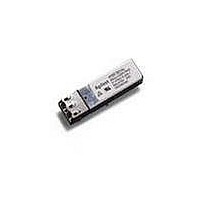
HFBR-59L1AL Avago Technologies US Inc., HFBR-59L1AL Datasheet

HFBR-59L1AL
Specifications of HFBR-59L1AL
Available stocks
Related parts for HFBR-59L1AL
HFBR-59L1AL Summary of contents
Page 1
... GBd Ethernet and 1.0625 GBd Fibre Channel 850 nm SFF Low Voltage (3.3 V) Optical Transceiver Data Sheet Description The HFBR-59L1AL from Avago Technologies is a high per- formance, cost-effective optical transceiver for serial op- tical data communications applications operating at 1.25 Gb/s and 1.0625 Gb/s. This module is designed for multi- mode fi ...
Page 2
... These transceivers are compatible with industry standard wave or hand solder processes. Recommended Solder Fluxes Type Solder fluxes used with the HFBR-59L1AL should be wa- tersoluble, organic fluxes. Recommended solder fluxes Ground include Lonco 3355-11 from London Chemical West, Inc. ...
Page 3
... The transceiver is compat- ible with an “ac-coupled” configuration and is internally terminated. Figure 1 depicts the functional diagram of the 3 HFBR-59L1AL. Caution should be taken to account for the proper interconnection between the supporting Physical Layer integrated circuits and the HFBR-59L1AL. Figure 3 illustrates the recommended interface circuit. ...
Page 4
... Business Equipment. 4 tion of the HFBR-59L1AL to a non-approved optical source, operating above the recommended absolute maximum conditions or operating the HFBR-59L1AL in a manner in- consistent with its design and function may result in haz- ardous radiation exposure and may be considered an act of modifying or manufacturing a laser product. ...
Page 5
... SI– 1 μH 1 μH 3.3 V 0.1 μF 10 μ 0.1 μF 9.0 KΩ 0.01 μF TD+ LASER DRIVER 100 Ω & SAFETY TD– CIRCUITRY TX GND 0.01 μ 0.1 50 Ω μF 0.01 μF RD+ AMPLIFICATION RD– & QUANTIZATION 0.01 μF Rx_SD 1.2 KΩ RX GND 50 Ω HFBR-59L1AL ...
Page 6
Table 2. Pin Description Pin Name RD Disable 9 TD+ 10 TD- Notes: 1. Transmitter and Receiver ...
Page 7
Table 3. Absolute Maximum Ratings Parameter Storage Temperature Case Temperature Relative Humidity Supply Voltage Data/Control Input Voltage Sense Output CurrentSignal Detect [SD] Notes: 1. Absolute Maximum Ratings are those values beyond which damage to the device may occur if these ...
Page 8
... DJ and TJ for the receiver at each data rate. In that table found from TJ –DJ, where the RX input jitter is noted as Gamma R, and the Rx output jitter is noted as Delta R. The HFBR-59L1AL contributed jitter is such that, if the maximum specified input jitter is present, and is combined with our maximum contributed jitter, then we meet the specifi ...
Page 9
... DJ and TJ for the transmitter at each data rate. In that table found from TJ – DJ, where the TX input jitter is noted as Delta T, and the TX output jitter is noted as Gamma T. The HFBR-59L1AL contributed jitter is such that, if the maximum specified input jitter is present, and is combined with our maximum contributed jitter, then we meet the specified maximum output jitter limits listed in the FC-PI MM jitter specifi ...
Page 10
... Gb/s Stressed receiver vertical eye closure penalty (ISI) min is 0.96 dB for 50 μm fiber and 2.18 dB for 62.5 μm fiber. Stressed receiver DCD component min (at TX ps. 5. These average power values are specified with an Extinction Ratio of 9 dB. The Signal Detect circuitry responds to OMA (peak-to-peak) power, not to average power. 6. Please refer to the HFBR-59L1AL characterization report for typical values. Transmitter Timing Characteristics Table 10 -10° ...
Page 11
V CC > 2.97 V Tx_FAULT Tx_DISABLE TRANSMITTED SIGNAL t_init - Tx_FAULT Tx_DISABLE TRANSMITTED ...
Page 12
... MAX. (0.535) 9.80 MAX. (0.39) 3.25 (0.128) 2.92 MIN. (0.115) 10.16 (0.400) DIMENSIONS ARE IN MILLIMETERS (INCHES) Figure 6a. Module drawing 12 AVAGO HFBR-59L1AL 850 nm LASER PROD 21CFR(J) CLASS 1 COUNTRY OF ORIGIN YYWW XXXXXX THERMOCOUPLE TEST POINT 48.19 (1.897) 13.63 (0.537) 14.68 1. (0.578) (0.039) 4 ...
Page 13
... The hatched areas are keep-out areas reserved for housing standoffs. No metal traces allowed in keep-out areas.. 3. The drawing shows extra pin holes for 2x10 pin transceivers. These extra holes are not required for HFBR-59L1AL. 4. Holes for mounting studs must be tied to chassis ground. ...


