HFBR-59L1AL Avago Technologies US Inc., HFBR-59L1AL Datasheet - Page 6
HFBR-59L1AL
Manufacturer Part Number
HFBR-59L1AL
Description
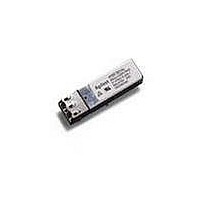
TXRX MMF SFP PTH FIBRE CHANNEL
Manufacturer
Avago Technologies US Inc.
Datasheet
1.HFBR-59L1AGEZ.pdf
(13 pages)
Specifications of HFBR-59L1AL
Data Rate
1.25Gbd
Wavelength
850nm
Applications
General Purpose
Voltage - Supply
2.97 V ~ 3.63 V
Connector Type
LC Duplex
Mounting Type
Through Hole
Function
Designed for use in short reach multimode fiber optic 1000BASE-SX and Fiber Channel, wide voltage and temperature operation.
Product
Transceiver
Maximum Rise Time
200 ps, 150 ps
Maximum Fall Time
200 ps, 150 ps
Pulse Width Distortion
0.147 ns, 0.17 ns
Operating Supply Voltage
2.97 V to 3.63 V
Maximum Operating Temperature
+ 85 C
Minimum Operating Temperature
- 10 C
Package / Case
DIP-10 with Connector
Lead Free Status / RoHS Status
Contains lead / RoHS non-compliant
Available stocks
Company
Part Number
Manufacturer
Quantity
Price
Company:

Part Number:
HFBR-59L1ALZ
Manufacturer:
M/A-COM
Quantity:
5 000


Table 2. Pin Description
Notes:
1. Transmitter and Receiver Ground are common in the internal module PCB. They are electrically connected to signal ground within the module,
2. TX disable input is used to shut down the laser output per the state table below. It is pulled down internally within the module with a 9.0 K:
3. SD (Signal Detect) is a normally high LVTTL output. When high it indicates that the received optical power is adequate for normal operation. When
4. RD-/+: These are the differential receiver outputs. They are ac coupled 100 : differential lines which should be terminated with 100 : differential
5. V
6
Pin
1
2
3
4
5
6
7
8
9
10
and to the housing shield (see Note 5 in Figure 7c). This housing shield is electrically isolated from the nose shield which is connected to chassis
ground (see Note 4 in Figure 7c).
resistor.
Low (0 – 0.8 V):
Between (0.8 V and 2.0 V):
High (2.0 – 3.465 V):
Open:
Low, it indicates that the received optical power is below the worst case receiver sensitivity, a fault has occurred, and the link is no longer valid.
at the user SerDes. The ac coupling is done inside the module and is thus not required on the host board. The voltage swing on these lines will be
between 400 and 2000 mV differential (200 – 1000 mV single ended) when properly terminated. These levels are compatible with CML and LVPECL
voltage swings.
current is 200 mA.
CC
R and V
CC
T are the receiver and transmitter power supplies. They are defined as 2.97 – 3.63 V at the PTH connector pin. The maximum supply
Name
V
V
SD
RD-
RD+
V
V
TX Disable
TD+
TD-
EE
CC
CC
EE
R
T
R
T
Transmitter on
Undefined
Transmitter Disabled
Transmitter Enabled
Function/Description
Receiver Ground
Receiver Power: 3.3 V ±10%
Signal Detect: Low indicates Loss of Signal
Inverse Received Data Out
Received Data Out
Transmitter Power: 3.3V ±10%
Transmitter Ground
Transmitter Disable: Module disables on High
Transmitter Data In
Inverse Transmitter Data In
MSA Notes
1
5
3
4
4
5
1
2
Related parts for HFBR-59L1AL
Image
Part Number
Description
Manufacturer
Datasheet
Request
R

Part Number:
Description:
RECEIVER FIBER OPTIC 600NM 40KBD
Manufacturer:
Avago Technologies US Inc.
Datasheet:

Part Number:
Description:
XMITTER FIBER OPTIC 600NM 5MBD
Manufacturer:
Avago Technologies US Inc.
Datasheet:

Part Number:
Description:
XMITTER FIBER OPTIC 600NM 40KBD
Manufacturer:
Avago Technologies US Inc.
Datasheet:

Part Number:
Description:
XMITTER VERSATILE LINK HORZ
Manufacturer:
Avago Technologies US Inc.
Datasheet:

Part Number:
Description:
XMITTER OPT HI PERFORMANCE VERT
Manufacturer:
Avago Technologies US Inc.
Datasheet:

Part Number:
Description:
TXRX FIBER OPTIC 650NM 10MBAUD
Manufacturer:
Avago Technologies US Inc.
Datasheet:
Part Number:
Description:
TXRX FIBER OPTIC 650NM 10MBAUD
Manufacturer:
Avago Technologies US Inc.
Datasheet:

Part Number:
Description:
FIBER OPTIC TRANSMITTER 660NM
Manufacturer:
Avago Technologies US Inc.
Datasheet:

Part Number:
Description:
KIT EVAL FIBER OPTIC 5MBD
Manufacturer:
Avago Technologies US Inc.
Datasheet:
Part Number:
Description:
KIT EVAL FIBER OPTICS 32MBD
Manufacturer:
Avago Technologies US Inc.
Datasheet:

Part Number:
Description:
KIT EVAL FIBER OPTIC 5MBD
Manufacturer:
Avago Technologies US Inc.
Datasheet:

Part Number:
Description:
125MBd 1300nm FiberOptic Eval Kit
Manufacturer:
Avago Technologies US Inc.
Datasheet:

Part Number:
Description:
DC-5MBd 820nm FiberOptic EvalKit
Manufacturer:
Avago Technologies US Inc.
Datasheet:
Part Number:
Description:
125MBd 820nm FiberOptic Eval Kit
Manufacturer:
Avago Technologies US Inc.
Datasheet:
Part Number:
Description:
DC-5MBd 650nm POF Eval Kit
Manufacturer:
Avago Technologies US Inc.
Datasheet: