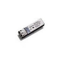
HFBR-59L1AL Avago Technologies US Inc., HFBR-59L1AL Datasheet - Page 2

HFBR-59L1AL
Manufacturer Part Number
HFBR-59L1AL
Description
TXRX MMF SFP PTH FIBRE CHANNEL
Manufacturer
Avago Technologies US Inc.
Datasheet
1.HFBR-59L1AGEZ.pdf
(13 pages)
Specifications of HFBR-59L1AL
Data Rate
1.25Gbd
Wavelength
850nm
Applications
General Purpose
Voltage - Supply
2.97 V ~ 3.63 V
Connector Type
LC Duplex
Mounting Type
Through Hole
Function
Designed for use in short reach multimode fiber optic 1000BASE-SX and Fiber Channel, wide voltage and temperature operation.
Product
Transceiver
Maximum Rise Time
200 ps, 150 ps
Maximum Fall Time
200 ps, 150 ps
Pulse Width Distortion
0.147 ns, 0.17 ns
Operating Supply Voltage
2.97 V to 3.63 V
Maximum Operating Temperature
+ 85 C
Minimum Operating Temperature
- 10 C
Package / Case
DIP-10 with Connector
Lead Free Status / RoHS Status
Contains lead / RoHS non-compliant
Available stocks
Company
Part Number
Manufacturer
Quantity
Price
Company:
Part Number:
HFBR-59L1ALZ
Manufacturer:
M/A-COM
Quantity:
5 000
Figure 2. Module pin assignments and pin configuration
Figure 1. Transceiver functional diagram. (See Process Compatibility Specifications)
Module Package
Avago offers the Pin Through Hole package utilizing an
integral LC Duplex optical interface connector. The trans-
ceiver uses a reliable 850 nm VCSEL source and requires a
3.3 V dc power supply for optimal system design.
Module Diagrams
Figure 1 illustrates the major functional components of
the HFBR-59L1AL. The connection diagram for both mod-
ules are shown in Figure 2. Figures 6a and 6b depict the
external configuration and dimensions of the module.
2
10
HFBR-59L1AL BLOCK DIAGRAM
6
7
8
9
OPTICAL INTERFACE
TOP VIEW
TX
LIGHT FROM FIBER
RX
LIGHT TO FIBER
5
4
3
2
1
Pin Description
Pin
1
2
3
4
5
6
7
8
9
10
Name
RX Ground
RX Power
RX SD
RX Data Bar
RX Data
TX Power
TX Ground
TX Disable
TX Data
TX Data Bar
RECEIVER
TRANSMITTER
PHOTO-DETECTOR
VCSEL
Type
Ground
Power
Status Out
Signal Out
Signal Out
Power
Ground
Control In
Signal In
Signal In
AMPLIFICATION
& QUANTIZATION
Installation
The HFBR-59L1AL can be installed in any MSA compli-
ant Pin Through Hole port. The module Pin Description is
shown in Figure 2.
Solder and Wash Process Capability
These transceivers are delivered with protective process
plugs inserted into the LC connector receptacle. This pro-
cess plug protects the optical subassemblies during wave
solder and aqueous wash processing and acts as a dust
cover during shipping. These transceivers are compatible
with industry standard wave or hand solder processes.
Recommended Solder Fluxes
Solder fluxes used with the HFBR-59L1AL should be wa-
tersoluble, organic fluxes. Recommended solder fluxes
include Lonco 3355-11 from London Chemical West, Inc.
of Burbank, CA, and 100 Flux from Alpha-Metals of Jersey
City, NJ.
Recommended Cleaning/Degreasing Chemicals
Alcohols: methyl, isopropyl, isobutyl.
Aliphatics: hexane, heptane.
Other: naphtha. Do not use partially halogenated hydro-
carbons such as 1,1.1 trichoroethane or ketones such as
MEK, acetone, chloroform, ethyl acetate, methylene di-
chloride, phenol, methylene chloride, or N-methylpyroll-
done.
Also, Avago does not recommend the use of cleaners that
use halogenated hydrocarbons because of their potential
environmental harm.
CIRCUITRY
DRIVER &
SAFETY
LASER
RD+ (RECEIVE DATA)
RD– (RECEIVE DATA)
SIGNAL DETECT
Tx_DISABLE
TD+ (TRANSMIT DATA)
TD– (TRANSMIT DATA)
ELECTRICAL INTERFACE


