HFBR-1533Z Avago Technologies US Inc., HFBR-1533Z Datasheet - Page 14
HFBR-1533Z
Manufacturer Part Number
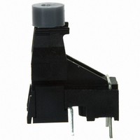
HFBR-1533Z
Description
XMITTER FIBER OPTIC VERT 40KBD
Manufacturer
Avago Technologies US Inc.
Specifications of HFBR-1533Z
Wavelength
600nm
Voltage - Forward (vf) Typ
2.02V
Current - Dc Forward (if)
1A
Voltage - Dc Reverse (vr) (max)
5V
Capacitance
86pF
Connector Type
Versatile Link
Data Rate Max
4Mbps
Forward Current If
80mA
Forward Voltage
1.67V
Reverse Voltage Vr
5V
Data Transmission Distance
120ft
Wavelength Typ
660nm
Peak Reflow Compatible (260 C)
Yes
Fiber Material
Plastic
Leaded Process Compatible
Yes
Rohs Compliant
Yes
Lead Free Status / RoHS Status
Lead free / RoHS Compliant
Spectral Bandwidth
-
Lead Free Status / RoHS Status
Lead free / RoHS Compliant, Lead free / RoHS Compliant
Other names
516-2050


HFBR-25X2Z/25X4Z Receivers
DO NOT CONNECT
DO NOT CONNECT
Absolute Maximum Ratings
Notes:
1. 1.6 mm below seating plane.
2. It is essential that a bypass capacitor 0.1 μF be connected from pin 2 to pin 3 of the receiver. Total lead length between both ends of the
Receiver Electrical/Optical Characteristics
Notes:
1. Measured at the end of the fiber optic cable with large area detector.
2. Pulsed LED operation at I
3. The LED drive circuit of Figure 11 is required for 1 MBd operation of the HFBR-25X2Z/25X4Z.
4. Optical flux, P (dBm) = 10 Log [P(μW)/1000 μW].
5. R
14
Parameter
Storage Temperature
Operating Temperature
Lead Soldering Cycle
Supply Voltage
Output Collector Current
Output Collector Power Dissipation
Output Voltage
Pull-up Voltage
Fan Out (TTL)
Parameter
Receiver
Optical Input
Power Level
Logic 0
Optical Input Power
Level Logic 1
High Level Output Current
Low Level Output Voltage
High Level Supply Current
Low Level Supply Current
Effective Diameter
Numerical Aperture
Internal Pull-up Resistor
capacitor and the pins should not exceed 20 mm.
width distortion of the receiver output signal.
L
is open.
5
8
HFBR-2522Z
HFBR-2524Z
F
> 80 mA will cause increased link t
1000 Ω
4
3
2
1
Temp.
Time
R
V
GROUND
V
Symbol
CC
O
L
P
P
I
I
V
I
NA
CCH
CCL
R(H)
OH
R
R(L)
D
OL
L
0°C to 70°C, 4.75 V ≤V
Min.
680
–24
–20
Symbol
PLH
I
P
V
OAV
V
V
T
T
N
OD
CC
propagation delay time. This extended t
A
S
O
P
1000
Typ.
0.4
3.5
6.2
0.5
5
1
Note: Pins 5 and 8 are for mounting and retaining purposes only. Do not
electrically connect these pins.
CC
Pin #
1
2
3
4
5
8
≤5.25 V unless otherwise specified.
1700
Max.
250
-43
0.5
6.3
Min.
–0.5
–0.5
10
–40
–40
–5
Units
dBm
dBm
mm
mA
mA
μA
Ω
V
Function
V
Ground
V
R
Do not connect
Do not connect
O
CC
Max.
L
+85
+85
260
V
10
25
40
18
7
5
CC
V
I
V
I
V
I
P
V
P
V
P
OL
OH
OL
OL
OH
CC
R
R
R
O
CC
= P
= 0
= -12.5 dBm
= 18 V, P
= 8 mA
= 8 mA
= ≤250 μA
= 5.25 V,
= 0 V
Conditions
= 5.25 V,
= 5.25 V
PLH
R(L)MIN
time contributes to increased pulse
Units
mW
sec
mA
°C
°C
°C
V
V
V
R
= 0
Reference
Note 1
Note 2
Notes 1, 2, 3
Note 4
Note 5
Note 5
Note 5
Note 5
Ref.
Related parts for HFBR-1533Z
Image
Part Number
Description
Manufacturer
Datasheet
Request
R

Part Number:
Description:
XMITTER FIBER OPTIC SERCOS SMA
Manufacturer:
Avago Technologies US Inc.
Datasheet:

Part Number:
Description:
FIBER OPTIC CBL SIMPLEX 1=100M
Manufacturer:
Avago Technologies US Inc.
Datasheet:

Part Number:
Description:
FIBER OPTIC CBL SIMPLEX 1=500M
Manufacturer:
Avago Technologies US Inc.
Datasheet:

Part Number:
Description:
FIBER OPTIC CONN LATCH GRY SIMPL
Manufacturer:
Avago Technologies US Inc.
Datasheet:

Part Number:
Description:
FIBER OPTIC CONN LATCH BLU SIMPL
Manufacturer:
Avago Technologies US Inc.
Datasheet:

Part Number:
Description:
XMITTER VERSATILE LINK HORZ
Manufacturer:
Avago Technologies US Inc.
Datasheet:

Part Number:
Description:
Fiber Optic Transmitters, Receivers, Transceivers 1300nm 155MBd 16-pin DIP ST Rx
Manufacturer:
Avago Technologies US Inc.

Part Number:
Description:
FIBER OPTIC CBL DUPLEX 1=100M
Manufacturer:
Avago Technologies US Inc.
Datasheet:
Part Number:
Description:
FIBER OPTIC CBL SIMPLEX 1=500M
Manufacturer:
Avago Technologies US Inc.
Datasheet:
Part Number:
Description:
FIBER OPTIC CBL DUPLEX 1=500M
Manufacturer:
Avago Technologies US Inc.
Datasheet:

Part Number:
Description:
OPTOCOUPLER GATE DRV 2A 16-SOIC
Manufacturer:
Avago Technologies US Inc.
Datasheet:
Part Number:
Description:
OPTOCOUPLER 2CH 2.5A 16-SOIC
Manufacturer:
Avago Technologies US Inc.
Datasheet:

Part Number:
Description:
OPTOCOUPLER GATE DRV 0.4A 16SOIC
Manufacturer:
Avago Technologies US Inc.
Datasheet:

Part Number:
Description:
OPTOCOUPLER 2.0A 250KHZ 8-DIP
Manufacturer:
Avago Technologies US Inc.
Datasheet:

Part Number:
Description:
OPTOCOUPLER 2.0A 250KHZ GW 8-SMD
Manufacturer:
Avago Technologies US Inc.
Datasheet: