HSMC-A101-S00J1 Avago Technologies US Inc., HSMC-A101-S00J1 Datasheet
HSMC-A101-S00J1
Specifications of HSMC-A101-S00J1
Available stocks


Related parts for HSMC-A101-S00J1


HSMC-A101-S00J1 Summary of contents
Page 1
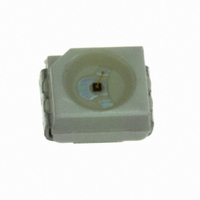
HSMx-A10x-xxxxx PLCC-2 Surface Mount LED Indicator Data Sheet Description This family of SMT LEDs is packaged in the industry standard PLCC-2 package. These SMT LEDs have high reliability performance and are designed to work under a wide range of environmental ...
Page 2
Package Dimensions 2.8 ± 0.2 2.2 ± 0.2 3.2 ± 0.2 CATHODE MARKING (ANODE MARKING FOR AlGaAs DEVICES) TOP MOUNT 2.8 ± 0.2 2.2 ± 0.2 3.2 ± 0.2 CATHODE MARKING REVERSE MOUNT NOTE: ALL DIMENSIONS IN MILLIMETERS. 2 1.9 ...
Page 3
... Min IV (mcd) HSMS-A100-J00J1 4.50 HSMS-A100-L00J1 11.20 HSMS-A100-H70J2 3.55 HSMS-A100-J80J2 5.60 HSMH-A100-L00J1 11.20 HSMH-A100-N00J1 28.50 HSMH-A100-M80J2 22.40 HSMC-A100-Q00J1 71.50 HSMC-A100-R00J1 112.50 HSMC-A101-S00J1 180.00 HSMZ-A100-T00J1 285.00 HSMC-A100-P30J1 45.00 Red Orange Part Number Min IV (mcd) HSMJ-A100-Q00J1 71.50 HSMJ-A101-S00J1 180.00 HSMV-A100-T00J1 285.00 HSMJ-A100-R40J1 112.50 HSMV-A100-S80J1 224.00 ...
Page 4
Yellow / Amber Part Number Min IV (mcd) HSMY-A100-J00J1 4.50 HSMY-A100-L00J1 11.20 HSMY-A100-J35J2 4.50 HSMA-A100-Q00J1 71.50 HSMA-A101-S00J1 180.00 HSMU-A100-S00J1 180.00 HSMA-A101-R8WJ1 140.00 HSMU-A100-S4WJ1 180.00 Yellow Green Part Number Min IV (mcd) HSMG-A100-J02J1 4.50 HSMG-A100-K72J2 9.00 HSME-A100-M02J1 18.00 HSME-A100-N82J1 35.50 Emerald ...
Page 5
... Duty factor = 10%, Frequency = 1 kHz. 3. Drive current between 10 mA and recommended for best long term performance. 4. Operation at current below not recommended Packaging Option Color Bin Selection Intensity Bin Select Device Specific Configuration Package Type LED Chip Color HSMH HSMC/J/L/A HSME [3, 100 mA 100 mA 100 110° ...
Page 6
... Radiant intensity watts/steradian, may be calculated from the equation I e the luminous efficacy in lumens/watt. Electrical Characteristics (T = 25˚C) A Forward Voltage V (Volts Part Number Typ. HSMS/D/Y/G 2.2 HSMH 1.9 HSMC/J/L/A/E 1.9 HSMZ/V/U 2.2 HSMB 3.9 HSMM/K/N 3.4 6 Peak Dominant [1] Wavelength Wavelength O O (nm) (nm) ...
Page 7
... TEMPERATURE (°C) Figure 4b. Maximum Forward Current Vs. Solder Point Temperature. Derated based on T MAX = J 110°C, Rθ = 180°C/W or 280°C/ HSMS/D/Y/G HSMZ/V HSMH 15 HSMC/J/L/A/E HSMM/K/N 10 HSMB FORWARD VOLTAGE – V Figure 2. Forward current vs. forward voltage. 1.8 1.6 Gap AlInGaP 1.4 ...
Page 8
GaP/AlGaAs/ 0 AlInGaP -0.1 -0.2 InGaN/GaN -0.3 -100 - 100 150 TEMPERATURE – °C Figure 6. Forward voltage shift vs. temperature. 255 - 260 C 3 C/SEC. MAX. 217 C 200 C 150 ...
Page 9
TRAILER 200 mm MIN. FOR Ø 180 REEL. 200 mm MIN. FOR Ø 330 REEL. Figure 11. Tape leader and trailer dimensions. 4 ± 0.1 +0.1 Ø 1.5 –0 3.05 ± 0.1 Figure 12. Tape dimensions. 9 COMPONENT 480 mm ...
Page 10
LABEL AREA (111 mm) WITH DEPRESSION (0.25 mm) Figure 13. Reel dimensions. USER FEED DIRECTION PRINTED LABEL Figure 14. Reeling orientation 62.5 –2.5 ...
Page 11
Intensity Bin Select ( Individual reel will contain parts from one half bin only. X Min I Bin Full Distribution 2 2 half bins starting from ...
Page 12
Packaging Option ( Option Test Current Package Type Top Mount Top Mount Reverse Mount Reverse Mount Top Mount ...