AXA016A0X3 Lineage Power, AXA016A0X3 Datasheet - Page 12
AXA016A0X3
Manufacturer Part Number
AXA016A0X3
Description
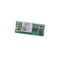
CONVER DC/DC 0.75 5.5V @ 16A SIP
Manufacturer
Lineage Power
Series
Austin SuperLynx™r
Type
Point of Load (POL) Non-Isolated with Remote On/Offr
Datasheet
1.AXA016A0X3Z.pdf
(19 pages)
Specifications of AXA016A0X3
Rohs Status
RoHS non-compliant
Output
0.75 ~ 5.5V
Number Of Outputs
1
Power (watts)
88W
Mounting Type
Through Hole
Voltage - Input
10 ~ 14V
Package / Case
10-SIP Module
1st Output
0.75 ~ 5.5 VDC @ 16A
Size / Dimension
2.00" L x 0.32" W x 0.50" H (50.8mm x 8.1mm x 12.7mm)
Power (watts) - Rated
88W
Operating Temperature
-40°C ~ 85°C
Efficiency
92%
Approvals
CSA, EN, UL, VDE
Product
Non-Isolated / POL
3rd Output
-
2nd Output
-
Lead Free Status / Rohs Status
Lead free / RoHS Compliant
Other names
555-1017
Available stocks
Company
Part Number
Manufacturer
Quantity
Price
Company:

Part Number:
AXA016A0X3
Manufacturer:
BCM
Quantity:
12
Company:
Part Number:
AXA016A0X3-SR
Manufacturer:
OKI
Quantity:
699
Part Number:
AXA016A0X3-SR
Manufacturer:
TYCO
Quantity:
20 000
Part Number:
AXA016A0X3-SRZ
Manufacturer:
TYCO
Quantity:
20 000


Data Sheet
October 1, 2009
Feature Description
Remote On/Off
The Austin SuperLynx
an On/Off pin for remote On/Off operation of the module.
If not using the remote On/Off pin, leave the pin open
(module will be On). The On/Off pin signal (Von/Off) is
referenced to ground. To switch the module on and off
using remote On/Off, connect an open collector npn
transistor or N-channel FET between the On/Off pin and
the ground pin (See Figure 27).
During a logic-high (On/Off pin is pulled high internal to
the module) when the transistor is in the Off state, the
power module is ON. The maximum allowable leakage
current of the transistor when Von/off = V
During a logic-low when the transistor is turned-on, the
power module is OFF. During this state VOn/Off is less
than 0.3V and the maximum IOn/Off = 1mA.
Figure 27. Remote On/Off Implementation.
Overcurrent Protection
To provide protection in a fault (output overload)
condition, the unit is equipped with internal
current-limiting circuitry and can endure current limiting
continuously. At the point of current-limit inception, the
unit enters hiccup mode. The unit operates normally once
the output current is brought back into its specified range.
The typical average output current during hiccup is 3A.
Input Undervoltage Lockout
At input voltages below the input undervoltage lockout
limit, module operation is disabled. The module will begin
to operate at an input voltage above the undervoltage
lockout turn-on threshold.
Overtemperature Protection
To provide protection in a fault condition, the unit is
equipped with a thermal shutdown circuit. The unit will
shutdown if the thermal reference point T
125
LINEAGE
o
I
C (typical), but the thermal shutdown is not
ON/OFF
GND
VIN+
POWER
ON/OFF
V
Q1
ON/OFF
+
_
TM
R1
12V SIP power modules feature
R2
R3
R4
10 – 14Vdc Input; 0.75Vdc to 5.5Vdc Output; 16A output current
Q2
IN,max
ref
Austin SuperLynx
MODULE
PWM Enable
Q3
, exceeds
is 10µA.
CSS
intended as a guarantee that the unit will survive
temperatures beyond its rating. The module will
automatically restarts after it cools down.
Output Voltage Programming
The output voltage of the Austin SuperLynx
be programmed to any voltage from 0.75Vdc to 5.5Vdc
by connecting a resistor (shown as Rtrim in Figure 28)
between the Trim and GND pins of the module.
Without an external resistor between the Trim and
GND pins, the output of the module will be 0.7525Vdc.
To calculate the value of the trim resistor, Rtrim for a
desired output voltage, use the following equation:
Rtrim is the external resistor in Ω
Vo is the desired output voltage
For example, to program the output voltage of the Austin
SuperLynx
follows:
Figure 28. Circuit configuration to program output
voltage using an external resistor.
Austin SuperLynx
applying a voltage between the TRIM and GND pins
(Figure 29). The following equation can be used to
determine the value of Vtrim needed to obtain a desired
output voltage Vo:
For example, to program the output voltage of a
SuperLynx
follows:
TM
12V SIP Non-isolated Power Modules:
V
ON/OFF
IN
Vtrim
Vtrim
(+)
TM
TM
GND
Rtrim
12V module to 1.8V, Rtrim is calculated as
module to 3.3 Vdc, Vtrim is calculated as
=
=
Rtrim
TM
(
0 (
0
V
TRIM
=
Rtrim
7 .
O
12Vdc can also be programmed by
7 .
Vtrim
(+)
⎡
⎢
⎣
=
−
Vo
−
⎡
⎢
⎣
. 0
. 0
1
10500
−
0667
8 .
0667
10500
=
=
. 0
−
. 9
. 0
7525
. 0
024
×
530
75
×
{
{
Vo
3
−
k
V
−
3 .
Ω
1000
1000
−
−
Rtrim
. 0
. 0
7525
⎤
⎥
⎦
7525
⎤
⎥
⎦
Ω
TM
}
)
}
12V can
)
LOAD
12
Related parts for AXA016A0X3
Image
Part Number
Description
Manufacturer
Datasheet
Request
R

Part Number:
Description:
Manufacturer:
Lineage Power
Datasheet: