FPSS1U TDK Corporation, FPSS1U Datasheet - Page 12
FPSS1U
Manufacturer Part Number
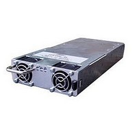
FPSS1U
Description
RACK 3 SLOT FOR FPS1000
Manufacturer
TDK Corporation
Series
FPSr
Specifications of FPSS1U
Accessory Type
Rack System
No. Of Slots
3
Peak Reflow Compatible (260 C)
No
External Width
19.00"
Rack U Height
1
External Depth
13.82"
For Use With
285-1239 - PWR SUP FNT END 48V 1008W 21A285-1238 - PWR SUP FNT END 32V 992W 31A285-1237 - PWR SUP FNT END 24V 960W 40A
Lead Free Status / RoHS Status
Lead free / RoHS Compliant
For Use With/related Products
FPS1000 Series
Lead Free Status / Rohs Status
RoHS Compliant part
Other names
285-1240
Available stocks
Company
Part Number
Manufacturer
Quantity
Price
Company:

Part Number:
FPSS1U
Manufacturer:
TDK-LAMBDA
Quantity:
232
Company:
Part Number:
FPSS1U/P
Manufacturer:
TDK-LAMBDA
Quantity:
232


3.7.3 Noise and Impedance Effects
To minimize the noise pickup or radiation, the load wires and remote sense wires should be twisted-pairs
of the shortest possible length. Shielding of the sense leads may be necessary in high noise environments.
between them, which might impact the stability of power supply. The sense leads should be separated
from the power leads.
Twisting the load wires reduces the parasitic inductance of the cable which could produce high frequency
voltage spikes at the load and the output of power supply because of current variation in the load itself.
The impedance introduced between the power supply output and the load could make the ripple and noise
at the load worse than the noise at the power supply rear panel output. Additional filtering with bypass
capacitors at the load terminals may be required to bypass the high frequency load current.
3.7.4 Inductive loads
To prevent damage to the power supply from inductive kickback, a diode should be connected across the
output. The diode voltage and current rating should be greater than the power supply maximum output
voltage and current rating. Connect the cathode to the positive output and the anode to the negative
output. Where positive load transients such as back EMF from a motor may occur, connect a surge
suppressor across the output to protect the power supply. The breakdown voltage rating of the suppressor
must be approximately 10% higher than the maximum output voltage of the power supply.
3.7.5 Making the load connections
Even if noise is not a concern, the load and remote sense wires should be twisted-pairs to reduce coupling
1
Fig. 3-1: FPS1000 front panel
Fig. 3-2: FPS1000/P front panel
1
3.7.6 Front panel controls and indicator
Hazardous voltages may exist at the outputs and the load connections
when using a power supply with a rated output greater than 40V. To protect
personnel against accidental contact with hazardous voltages, ensure that
the load and it's connections has no accessible live parts.
Ensure that the load wiring insulation rating is greater than or equal to the
maximum output voltage of the power supply.
2
2
3
3
4
4
6
!
WARNING
9
5
5
1: Handle
2: DC OK green LED, on when the output
3: DC Fail red LED, on when the output voltage
4: AC OK green LED, on when the input
5: Lock/Unlock lever. Automatically locks the
power supply to the FPS-S1U rack chassis
when the FPS1000 power supply is
inserted. Push the Lock/Unlock lever toward
the power supply cooling fan to withdraw
6: IEC320 AC inlet
voltage is above 80% +/- 5% of its rated value.
is lower than 80% +/- 5% of its rated value.
voltage is higher than 85Vrms
the FPS1000 from the rack.
FPS1000 Instruction Manual
Related parts for FPSS1U
Image
Part Number
Description
Manufacturer
Datasheet
Request
R

Part Number:
Description:
KIT F-SERIES CLIPS
Manufacturer:
PHIHONG USA
Datasheet:

Part Number:
Description:
TDK DC to DC Converters, DC to AC Inverters
Manufacturer:
TDK Corporation
Datasheet:
Part Number:
Description:
TDK DC to DC Converters, DC to AC Inverters
Manufacturer:
TDK Corporation
Datasheet: