FPSS1U TDK Corporation, FPSS1U Datasheet - Page 24
FPSS1U
Manufacturer Part Number
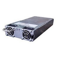
FPSS1U
Description
RACK 3 SLOT FOR FPS1000
Manufacturer
TDK Corporation
Series
FPSr
Specifications of FPSS1U
Accessory Type
Rack System
No. Of Slots
3
Peak Reflow Compatible (260 C)
No
External Width
19.00"
Rack U Height
1
External Depth
13.82"
For Use With
285-1239 - PWR SUP FNT END 48V 1008W 21A285-1238 - PWR SUP FNT END 32V 992W 31A285-1237 - PWR SUP FNT END 24V 960W 40A
Lead Free Status / RoHS Status
Lead free / RoHS Compliant
For Use With/related Products
FPS1000 Series
Lead Free Status / Rohs Status
RoHS Compliant part
Other names
285-1240
Available stocks
Company
Part Number
Manufacturer
Quantity
Price
Company:

Part Number:
FPSS1U
Manufacturer:
TDK-LAMBDA
Quantity:
232
Company:
Part Number:
FPSS1U/P
Manufacturer:
TDK-LAMBDA
Quantity:
232


7.4.3 Analog functions
Analog functions are provided by a single PCF8591, 4-channel 8-bit A/D converter. When this device is read by the
serial buscontroller it provides an 8-bit word with the following information:
Channel 1: Output voltage,
Value
Refer to the following table for the scaling of the A/D channels:
The measurement range is from 0 to the maximum value listed in the range column. The resolution or scale of
reading is linear over the entire range and provides a linear output on the A/D converter.
7.5 Measurements and calculation examples
7.5.1 Output voltage readback
The voltage before the "Oring" diode is measured and can be read from the A/D converter. This voltage is higher
than the voltage at the output terminals by 0.5V typically.
Model: FPS 1000-48/S
1. Output voltage (at the output terminals): 48.0V
2. Voltage before the "Oring" diode: 48.0V+0.5V=48.5V
3. .Hex readback: CE (1100 1110).
4. Convert the hex readback to decimal: 206
5. Calculate measured Vout: Vout=206*0.2344=48.286V
7.5.2 Output current readback
The output current is sensed by an internal shunt and measured by an A/D converter. Refer to the following examplefor
current readback calculation.
1. Actual output current: 21.0A
2. Hex readback: E0 (1110 0000).
3. Convert the hex readback to decimal: 224
4. Calculate measured Iout: Iout=224*0.0977=21.884A.
Value
The PCF8591 device initially requires a control byte to be written to the configuration register.
The control byte is as follows:
When a single channel is to be read, A,B,C and D should be determined as follows:
To read all channels with a single control byte, A and B have to be "1", C and D have to be "0". This control byte
sets the device so that on each successive read the data from the next A/D is read.Thus, the first result from a
sequence of reads should not be considered.
Note that on each read, a conversion is started for a particular channel and the result will be read from the previous channel.
7.4.4 A/D Scaling
The A/D readback has to be scaled to obtain a correct value for the voltage, current and the temperature. Note that
the voltage reading is made inside the power supply unit before the "Oring" diode and is typically 0.5V higher than
the actual output voltage.
The following scaling should be employed:
Bit
Bit
The PCF8591 slave address is:
FPS1000-12/S
FPS1000-32/S
A/D channel
Voltage
Current
Temperature
0~15V
0~80A
0~100°C
7
1
7
0
0.0586 V/Bit
0.312 A/Bit
0.391°C/Bit
A
6
0
6
channel 2: Output current,
A
0
0
0
5
0
5
0
B
0
0
0
VALUE = BYTE VALUE x RESOLUTION
21
4
1
4
0
FPS1000-24/S
FPS1000-48/S
C
0
0
1
channel 3: Internal temperature.
A2
3
0
3
D
0
1
0
FPS1000 Instruction Manual
A1
B
2
2
A0
C
1
1
R/W
D
0
0
Related parts for FPSS1U
Image
Part Number
Description
Manufacturer
Datasheet
Request
R

Part Number:
Description:
KIT F-SERIES CLIPS
Manufacturer:
PHIHONG USA
Datasheet:

Part Number:
Description:
TDK DC to DC Converters, DC to AC Inverters
Manufacturer:
TDK Corporation
Datasheet:
Part Number:
Description:
TDK DC to DC Converters, DC to AC Inverters
Manufacturer:
TDK Corporation
Datasheet: