7023-D-E-700 LEDdynamics Inc, 7023-D-E-700 Datasheet - Page 4
7023-D-E-700
Manufacturer Part Number
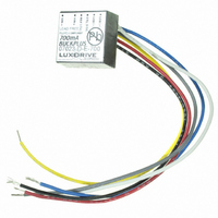
7023-D-E-700
Description
LED DVR BUCKPLUS 700MA 6LD DIM
Manufacturer
LEDdynamics Inc
Series
7023 BuckPlusr
Datasheet
1.7021HE.pdf
(8 pages)
Specifications of 7023-D-E-700
Voltage - Input
7 ~ 32V
Voltage - Output
32V
Current - Output
700mA
Power (watts)
22.4W
Mounting Type
Panel Mount
Termination Style
Wire Leads
Size / Dimension
0.83" L x 0.83" W x 0.43" H (21.08mm x 21.08mm x 10.92mm)
Operating Temperature
-40°C ~ 80°C
Lead Free Status / RoHS Status
Lead free / RoHS Compliant
Other names
788-1025


LEDdynamics, Inc.
802.728.4533 P
802.728.3800 F
sales@LUXdrive.com
www.LUXdrive.com
Adjustable Current - On-Board Control - “I” Model
Where the ability to adjust the output current to an intermediate value is required, all output current ratings are
available with an on-board potentiometer. This permits the output current to be varied from approximately 40%
to 110% of the rated value. When measuring the output is required to determine a particular set point, the
following method is recommended:
Because there is a small, high-frequency component in the 7021/7023 output, many multi-meters may give an
incorrect reading when used in the current mode. It has been found that the method described above yields a far
more accurate measurement.
The potentiometers used for the on-board adjustable units are rated for a limited number of rotations (typically
100) and are intended for "set it and forget it" applications. Where frequent adjustments of output current are
needed, the use of units with external adjustment capabilities is recommended.
Adjustable Current - External Control - “E” Model
Figures 10 and 11 show external adjustment configurations. Both use a 5Kohm, linear taper potentiometer. In
Figure 10, the potentiometer is connected between the internal 5V
input. When using this configuration, it is important that Vin be 7V
potentiometer being powered by an external 5V
potentiometer, the source ground must be common to the LED- output pin. In either configuration, connect the
potentiometer such that clockwise rotation increases the resistance. Note that, because the current through the
potentiometer is less than 5mA, a low power potentiometer may be used.
External On/Off Control
Where a manual on/off control is desired, the potentiometer in Figures 10 and 11 may be replaced by a pushbutton
or toggle switch. The output current will be zero when the switch is closed. Figures 12 and 13 show external
dimming control combined with on/off control. The circuit in Figure 13 uses a 2N3906 or equivalent PNP
switching transistor.
External Pulse/Strobe Control
Figures 14 and 15 show two methods for low speed pulsing or high speed flashing operation. In Figure 14, a
5V TTL/CMOS logic signal is applied directly to the control (Ctrl) input of the 7021/7023. The output current will be
zero when the control signal is high. Note that the input needs to source a minimum of 4.75V
input impedance. Also, as is the case with a dc control signal, the logic input ground should to be common to the
LED- output terminal.
Figure 15 shows an inverted input configuration using a 2N3906 or other PNP switching transistor. In this case, a
logic high will cause the output to be "on". In either configuration, the rise time of the output will be 10μsec or
less. A pulse frequency up to 10kHz may be used.
Temporarily place a 0.1 ohm, 1% resistor in series with the LEDs.
Read the voltage across the 0.1 ohm resistor.
The voltage, in millivolts X 10, will equal the output current in mA.
DC
source. When using an external power source for the
©2010 LUXdrive, A Division of LEDdynamics, Inc. www.LUXdrive.com.
Specifications subject to change without notice. April, 2010 - Rev 2.2
7021/7023 BuckPlus
DC
DC
Wide Range LED Power Module
reference (Ref) output and the control (Ctrl)
or higher. Figure 11 shows the control
DATA SHEET Page 4 of 8
DC
into a 1.5Kohm
TM
Related parts for 7023-D-E-700
Image
Part Number
Description
Manufacturer
Datasheet
Request
R

Part Number:
Description:
LED DVR BUCKPLUS 1000MA 6LD DIM
Manufacturer:
LEDdynamics Inc
Datasheet:

Part Number:
Description:
LED DVR BUCKPLUS 350MA 6LD DIM
Manufacturer:
LEDdynamics Inc
Datasheet:

Part Number:
Description:
LED DVR BUCKPLUS 500MA 6LD DIM
Manufacturer:
LEDdynamics Inc
Datasheet:

Part Number:
Description:
LED DVR BUCKPLUS 1000MA 4LEAD
Manufacturer:
LEDdynamics Inc
Datasheet:

Part Number:
Description:
LED DVR BUCKPLUS 350MA 4 LEAD
Manufacturer:
LEDdynamics Inc
Datasheet:

Part Number:
Description:
LED DVR BUCKPLUS 500MA 4 LEAD
Manufacturer:
LEDdynamics Inc
Datasheet:

Part Number:
Description:
LED DVR BUCKPLUS 700MA 4 LEAD
Manufacturer:
LEDdynamics Inc
Datasheet:

Part Number:
Description:
LED DVR BUCKPLUS 1000MA DIM/CUR
Manufacturer:
LEDdynamics Inc