ATSTK525 Atmel, ATSTK525 Datasheet
ATSTK525
Specifications of ATSTK525
Available stocks


Related parts for ATSTK525


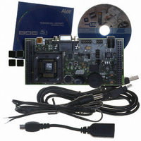
ATSTK525 Summary of contents
Page 1
STK525 ............................................................................................. Hardware User Guide ...
Page 2
STK525 Hardware User Guide User Guide Section 1 Introduction ........................................................................................... 1-3 1.1 Overview ...................................................................................................1-3 1.2 STK525 Starter Kit Features .....................................................................1-4 Section 2 Using the STK525................................................................................. 2-6 2.1 Overview ...................................................................................................2-6 2.2 Power Supply ............................................................................................2-7 2.3 RESET ....................................................................................................2-10 2.4 AT90USBxxx AVR Microcontroller..........................................................2-11 ...
Page 3
... To complement the evaluation and enable additional development capability, the STK525 can be plugged into the Atmel STK500 Starter Kit Board in order to use the AT90USBxxx with advanced features such as variable VCC, variable VRef, variable XTAL, etc. and supports all AVR development tools. ...
Page 4
Introduction 1.2 STK525 Starter Kit Features 1-4 7608A–AVR–04/06 Figure 1-1 . STK525 Board The STK525 provides the following features: AT90USBxxx TQFP device (2.7V<Vcc<5.5V), AVR Studio® software interface USB software interface for Device Firmware Upgrade (DFU bootloader) STK500 compatible Power supply ...
Page 5
... AVR Studio®, AVR tools and this User Guide can be found in the AVR section of the Atmel web site, http://www.atmel.com. 2. ATMEL Flip®, In System Programming Version 3 or Higher shall be used for Device Firmware Upgrade. Please consult Atmel web site to retrieve the latest version of Flip and the DFU bootloader Hex file if needed ...
Page 6
Overview STK525 Hardware User Guide This chapter describes the board and all its features. Figure 2-1 . STK525 Overview USB MiniAB RS232 C Sensor Pin1 LEDS TQFP64 Socket Crystal Microphone Using the STK525 JTAG ISP External Power Vcc Src. ...
Page 7
Power Supply 2.2.1 Power Supply Sources USB powered: When used as a USB device bus powered application, the STK525 can be powered via JACK PWR connector: STK500 Powered: (c.f. STK525 Hardware User Guide The on-board power supply circuitry allows ...
Page 8
Using the STK525 2.2.2 Power Supply Setting Vcc Source Jumper position VBUS 5 REG 5 REG 3.3 STK 2-8 7608A–AVR–04/06 (1) Table 2-1 . Power Supply Setting VCC power Comments supply value This is the default configuration. This should be ...
Page 9
VBUS Generator Setting “Vbus Gen” STK525 power supply Jumper position “Ext” External power supply from J6 External power supply from “Stk” Expand0/1 (connected to a STK500) STK525 Hardware User Guide When using the AT90USBxxx microcontroller in USB host mode. ...
Page 10
Using the STK525 2.2.4 “POWER-ON“ LED 2.3 RESET 2.3.1 Power-on RESET 2.3.2 RESET Push Button 2-10 7608A–AVR–04/06 The POWER-ON LED is always lit when power is applied to STK525 regardless of power supply source and the regulation. Figure 2-5 . ...
Page 11
STK500 RESET 2.4 AT90USBxxx AVR Microcontroller 2.4.1 Main Clock XTAL 2.4.2 Analog Power Supply AVCC By default, AVCC is equivalent to VCC. ANA REF By default, AREF is an output of AT90USBxxx. 2.5 Serial Links 2.5.1 USB STK525 Hardware ...
Page 12
Using the STK525 2.5.2 RS-232C 2-12 7608A–AVR–04/06 The AT90USBxxx is a microcontroller with an on-chip USART peripheral (USART1). Only the asynchronous mode is supported by the STK525. The STK525 is supplied with a RS-232 driver/receiver. One female DB9 connector assumes ...
Page 13
STK525 Hardware User Guide The STK525 USART implementation allows an optional hardware flow control that can be enabled thanks to SP4, SP5, SP7, SP8 solder pads (See Figure 2-11). Figure 2-11 . USART Schematic RS232 Interface C16 100nF C17 PD[7..0] ...
Page 14
Using the STK525 2.6 On-board Resources 2.6.1 Joystick 2.6.2 LEDs 2-14 7608A–AVR–04/06 The 4+1 way joystick offers an easy user interface implementation for a USB application (it can emulate mouse movements, keyboard inputs, etc.). Pushing a push-button causes the corresponding ...
Page 15
STK525 Hardware User Guide Figure 2-14 . LEDs Implementation Schematic In-line Grouped LEDs 1k R12 LED 0 (green) TOPLED LP M676 1k R13 LED 1 (green) TOPLED LP M676 1k R14 LED 2 (green) TOPLED LP M676 1k R15 LED ...
Page 16
Using the STK525 2.6.3 Temperature Sensor 2-16 7608A–AVR–04/06 The temperature sensor uses a thermistor (R18), or temperature-sensitive resistor. This thermistor has a negative temperature coefficient (NTC), meaning the resistance goes up as temperature goes down. Of all passive temperature measurement ...
Page 17
Microphone STK525 Hardware User Guide Temp. R Temp. T (°C) (KΩ) (°C) -9 627,604 21 -8 590,613 22 -7 556,056 23 -6 523,757 24 -5 493,555 25 -4 465,300 26 -3 438,854 27 -2 414,089 28 -1 390,890 29 ...
Page 18
Using the STK525 3.3V R20 2.2k C24 4.7uF MIC1 MICROPHONE 2.6.5 Data Flash Memory 2.6.6 Potentiometer 2-18 7608A–AVR–04/06 Figure 2-16 . Microphone interface schematic R23 100k R21 C22 220pF 100k U4A R25 10k LMV358 R28 ...
Page 19
STK500 Resources 2.7.1 Supply Voltage from STK500 2.7.2 Analog Reference Voltage from STK500 STK525 Hardware User Guide Figure 2-18 . Connecting STK525 to the STK500 Board Note: Caution: Do not mount an AVR microcontroller on the STK500 board when ...
Page 20
... AT90USBxxx. This is the easiest and fastest way to reprogram the device directly over the USB interface. The “Flip” PC side application available for free on Atmel website offers a flexible and user friendly interface to reprogram the application over the USB bus. ...
Page 21
Programming with AVR ISP mkII Programmer 2.8.3 Programming with STK500 STK525 Hardware User Guide The HWB pin of the AT90USBxxx allows to force the bootloader section execution after reset. (Refer to AT90USBxxx datasheet section “boot loader support”). To force ...
Page 22
Using the STK525 2.8.4 Programming with AVR JTAG ICE 2-22 7608A–AVR–04/06 To program the device using ISP from STK500, connect the 6-wire cable between the ISP6PIN connector of the STK500 board and the ISP connector of the STK525 as shown ...
Page 23
... Thus the on-chip flash bootloader will be erased. It can be restored after the debug session using the bootloader hex file available from ATMEL website. There are 8 test points implemented, these test points are referred in the full schematics section ...
Page 24
Using the STK525 2.11 Configuration Pads 2.11.1 Configuration Pads Listing 2.11.2 Configuration Pads - Disconnection 2.11.3 Configuration Pads - Connection 2-24 7608A–AVR–04/06 to Configuration pads are used disconnect/connect on-board peripherals or elements, their default configuration is: connect. Table 2-5 . ...
Page 25
Solder Pads 2.12.1 Solder Pads Listing STK525 Hardware User Guide Solder pads are used to disconnect/connect on-board peripherals or elements, their default configuration is: disconnect. Table 2-6 . Solder Pads Solder. Related Pads Signals Reference SP1 AVCC/VCC This solder ...
Page 26
STK525 Hardware User Guide Figure 3-1 . Troubleshooting Guide Problem The Green “VCC-ON” LED is not on No power supply STK525 does not work The STK500 ISP header is not connected. The AVR ISP probe is not connected The AVR ...
Page 27
STK525 Hardware User Guide Troubleshooting Guide 3-27 7608A–AVR–04/06 ...
Page 28
STK525 Hardware User Guide Technical Specifications System Unit – Physical Dimensions ................................................. L=119 x W=56 x H=27 mm – Weight ...........................................................................................................70 g Operating Conditions – Internal Voltage Supply .....................................................................2.7V - 5.5V – External Voltage Supply ..........................................................9V -15V (100mA) Connections – ...
Page 29
... STK525 Hardware User Guide For Technical support, please contact avr@atmel.com. When requesting technical support, please include the following information: Which target AVR device is used (complete part number) Target voltage and speed Clock source and fuse setting of the AVR Programming method (ISP, JTAG or specific Boot-Loader) Hardware revisions of the AVR tools, found on the PCB Version number of AVR Studio ...
Page 30
STK525 Hardware User Guide On the next pages, the following documents of STK525 revision 4381A are shown: Complete schematics, Assembly drawing, Bill of materials. Default configuration summary Section 6 Complete Schematics 6-30 7608A–AVR–04/06 ...
Page 31
PA2 49 PA2 PA1 50 PA1 PA0 51 PA0 VCC 52 GND 53 PF7 54 PF7 PF6 55 PF6 PF5 56 PF5 PF4 57 PF4 PF3 58 PF3 PF2 59 PF2 PF1 60 PF1 PF0 61 PF0 AREF 62 GND ...
Page 32
Complete Schematics 6-32 7608A–AVR–04/06 Figure 6-2 . Schematics STK525 Hardware User Guide ...
Page 33
STK525 Hardware User Guide Figure 6-3 . Schematics PF2 PF1 PF0 Complete Schematics 6-33 7608A–AVR–04/06 ...
Page 34
Complete Schematics 6-34 7608A–AVR–04/06 Figure 6-4 . Schematics GND STK525 Hardware User Guide ...
Page 35
STK525 Hardware User Guide Figure 6-5 . Assembly Drawing (component side) Figure 6-6 . Assembly Drawing (solder side) Complete Schematics 6-35 7608A–AVR–04/06 ...
Page 36
Complete Schematics Item Q. CR1,CR2 C1,C2,C3,C4,C5,C6,C13,C14,C15,C16 17,C18,C19,C20,C21,C23,C26,C27,C33 3 2 C7,C25 4 3 C8,C9,C32 5 2 C10,C11 6 1 C12 7 1 C22 8 5 C24,C28,C30,C31,C34 9 1 C29 10 3 CP1, CP2, CP3 ...
Page 37
Item Q. R10,R11,R16,R21,R22,R23,R24,R28,R33 34 5 R12,R13,R14,R15,R34 35 1 R18 36 1 R19 37 1 R19 Button 38 1 R20 39 1 R26 40 1 R30, R35 41 1 R31 42 6 SP1,SP2,SP3,SP4,SP5,SP6 43 2 SW1,SW2 44 1 SW3 ...
Page 38
Complete Schematics 6-38 7608A–AVR–04/06 Name Ref. Function SP1 Bypass L1 SP2 SP3 3.3V on Expand 0 NC pin SP4 CTS SP5 RTS SP6 Bypass limiter SP7 RS232 hardware control enable SP8 RS232 hardware control enable CP1 Bypass CTN in on ...
Page 39
... Disclaimer: The information in this document is provided in connection with Atmel products. No license, express or implied, by estoppel or otherwise,to anyintellectu- alproperty right is granted by this document or in connection with the sale of Atmel products. EXCEPT AS SET FORTH IN ATMEL’S TERMS AND CONDI-TIONS OF SALE LOCATED ON ATMEL’S WEB SITE, ATMEL ASSUMES NO LIABILITY WHATSOEVER AND DISCLAIMS ANY EXPRESS, IMPLIED OR STATUTORYWAR- RANTY RELATING TO ITS PRODUCTS INCLUDING, BUT NOT LIMITED TO, THE IMPLIED WARRANTY OF MERCHANTABILITY, FITNESS FOR A PARTICU- LARPURPOSE, OR NON-INFRINGEMENT ...