ATSTK525 Atmel, ATSTK525 Datasheet - Page 9
ATSTK525
Manufacturer Part Number
ATSTK525
Description
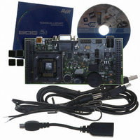
KIT STARTER FOR AT90USB
Manufacturer
Atmel
Specifications of ATSTK525
Accessory Type
STK500 Expansion Module
Processor To Be Evaluated
AT90USBxxx
Data Bus Width
8 bit
Interface Type
RS-232, USB
Silicon Manufacturer
Atmel
Core Architecture
AVR
Silicon Core Number
AT90USB
Kit Contents
Board Docs
Rohs Compliant
Yes
For Use With/related Products
AT90USB Devices
For Use With
ATEVK525 - ADD ON KIT FOR STK525ATSTK500 - PROGRAMMER AVR STARTER KIT
Lead Free Status / RoHS Status
Lead free / RoHS Compliant
Available stocks
Company
Part Number
Manufacturer
Quantity
Price
Company:

Part Number:
ATSTK525
Manufacturer:
Atmel
Quantity:
135


2.2.3
STK525 Hardware User Guide
Jumper position
“Vbus Gen”
VBUS Generator Setting
“Ext”
“Stk”
External power supply from J6
External power supply from
Expand0/1 (connected to a STK500)
STK525 power supply
When using the AT90USBxxx microcontroller in USB host mode. The STK525 should
provide a 5V power supply over the VBUS pin of its USB mini AB connector.
A couple of transistors on the STK525 allows the UVCON pin of the AT90USBxxx to
control the VBUS generation (See Figure 2-4). In this mode the STK525 is powered by
external power supply source (J6 or STK500 expand0/1 connectors). JP7 allows to
select the 5V source used by the VBUS generator.
Figure 2-4 . VBUS generator schematic
Table 2-2 . VBUS Generator Setting
UVCON
VTG
STK
Ext
This is the default configuration.
The VBUS generator source is the
on-board 5V regulator.
The VBUS generator source is the
STK500.
Note:
The “Vtarget” setting of STK500
should be set to “5V”.
1
3
VBUS gen
R33
100k
JP7
2
Comments
R32
10k
Q2
BC847B
M1
FDV304P/FAI
-
C34
4.7uF
VBUS
Vbus
Vbus
View
Gen
Gen
Using the STK525
7608A–AVR–04/06
2-9
Related parts for ATSTK525
Image
Part Number
Description
Manufacturer
Datasheet
Request
R

Part Number:
Description:
DEV KIT FOR AVR/AVR32
Manufacturer:
Atmel
Datasheet:

Part Number:
Description:
INTERVAL AND WIPE/WASH WIPER CONTROL IC WITH DELAY
Manufacturer:
ATMEL Corporation
Datasheet:
Part Number:
Description:
Low-Voltage Voice-Switched IC for Hands-Free Operation
Manufacturer:
ATMEL Corporation
Datasheet:
Part Number:
Description:
MONOLITHIC INTEGRATED FEATUREPHONE CIRCUIT
Manufacturer:
ATMEL Corporation
Datasheet:
Part Number:
Description:
AM-FM Receiver IC U4255BM-M
Manufacturer:
ATMEL Corporation
Datasheet:
Part Number:
Description:
Monolithic Integrated Feature Phone Circuit
Manufacturer:
ATMEL Corporation
Datasheet:
Part Number:
Description:
Multistandard Video-IF and Quasi Parallel Sound Processing
Manufacturer:
ATMEL Corporation
Datasheet:
Part Number:
Description:
High-performance EE PLD
Manufacturer:
ATMEL Corporation
Datasheet:
Part Number:
Description:
8-bit Flash Microcontroller
Manufacturer:
ATMEL Corporation
Datasheet:
Part Number:
Description:
2-Wire Serial EEPROM
Manufacturer:
ATMEL Corporation
Datasheet: