MA330013 Microchip Technology, MA330013 Datasheet - Page 85
MA330013
Manufacturer Part Number
MA330013
Description
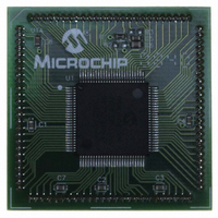
MODULE PLUG-IN DSPIC33 100TQFP
Manufacturer
Microchip Technology
Specifications of MA330013
Accessory Type
Plug-In Module (PIM) - dsPIC33FJ256MC710
Tool / Board Applications
General Purpose MCU, MPU, DSP, DSC
Mcu Supported Families
DsPIC33
Silicon Manufacturer
Microchip
Core Architecture
DsPIC
Core Sub-architecture
DsPIC33
Silicon Core Number
DsPIC33F
Silicon Family Name
DsPIC33FJxxMCxxx
Rohs Compliant
Yes
For Use With
DM330023 - BOARD DEV DSPICDEM MCHV
Lead Free Status / RoHS Status
Not applicable / Not applicable
For Use With/related Products
Explorer 16 (DM240001 or DM240002)
Lead Free Status / RoHS Status
Lead free / RoHS Compliant, Not applicable / Not applicable


5.0
The Reset module combines all Reset sources and
controls the device Master Reset Signal, SYSRST. The
following is a list of device Reset sources:
• POR: Power-on Reset
• BOR: Brown-out Reset
• MCLR: Master Clear Pin Reset
• SWR: RESET Instruction
• WDT: Watchdog Timer Reset
• TRAPR: Trap Conflict Reset
• IOPUWR: Illegal Opcode and Uninitialized W
A simplified block diagram of the Reset module is
shown in Figure 5-1.
Any active source of Reset will make the SYSRST sig-
nal active. Many registers associated with the CPU and
peripherals are forced to a known Reset state. Most
registers are unaffected by a Reset; their status is
unknown on POR and unchanged by all other Resets.
FIGURE 5-1:
© 2007 Microchip Technology Inc.
Note:
Register Reset
RESETS
This data sheet summarizes the features
of this group of dsPIC33F devices. It is not
intended to be a comprehensive reference
source. To complement the information in
this data sheet, refer to the “dsPIC30F
Family Reference Manual” (DS70046).
MCLR
V
DD
Uninitialized W Register
RESET SYSTEM BLOCK DIAGRAM
RESET Instruction
Sleep or Idle
Illegal Opcode
Module
WDT
Trap Conflict
V
Regulator
Detect
DD
Internal
Rise
Glitch Filter
POR
BOR
Preliminary
All types of device Reset will set a corresponding status
bit in the RCON register to indicate the type of Reset
(see Register 5-1). A POR will clear all bits, except for
the POR bit (RCON<0>), that are set. The user can set
or clear any bit at any time during code execution. The
RCON bits only serve as status bits. Setting a particular
Reset status bit in software does not cause a device
Reset to occur.
The RCON register also has other bits associated with
the Watchdog Timer and device power-saving states.
The function of these bits is discussed in other sections
of this manual.
Note:
Note:
Refer to the specific peripheral or CPU
section of this manual for register Reset
states.
The status bits in the RCON register
should be cleared after they are read so
that the next RCON register value after a
device Reset will be meaningful.
dsPIC33F
SYSRST
DS70165E-page 83
Related parts for MA330013
Image
Part Number
Description
Manufacturer
Datasheet
Request
R

Part Number:
Description:
Manufacturer:
Microchip Technology Inc.
Datasheet:
Part Number:
Description:
Manufacturer:
Microchip Technology Inc.
Datasheet:
Part Number:
Description:
Manufacturer:
Microchip Technology Inc.
Datasheet:
Part Number:
Description:
Manufacturer:
Microchip Technology Inc.
Datasheet:
Part Number:
Description:
Manufacturer:
Microchip Technology Inc.
Datasheet:
Part Number:
Description:
Manufacturer:
Microchip Technology Inc.
Datasheet:
Part Number:
Description:
Manufacturer:
Microchip Technology Inc.
Datasheet:
Part Number:
Description:
Manufacturer:
Microchip Technology Inc.
Datasheet: