27220 Parallax Inc, 27220 Datasheet - Page 168

27220
Manufacturer Part Number
27220
Description
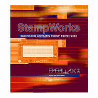
BOOK STAMPWORKS
Manufacturer
Parallax Inc
Datasheet
1.27220.pdf
(230 pages)
Specifications of 27220
Accessory Type
Booklet
Product
Microcontroller Accessories
Lead Free Status / RoHS Status
Not applicable / Not applicable
For Use With/related Products
StampWorks
Lead Free Status / RoHS Status
Lead free / RoHS Compliant, Not applicable / Not applicable
- Current page: 168 of 230
- Download datasheet (3Mb)
Page 158 · StampWorks
Behind the Scenes
Previous projects have used RCTIME to read resistive components. This is a form of
analog input, but isn’t voltage measurement. For that, the BASIC Stamp needs help
from an external device. The simplest way to measure a variable voltage is with an
analog-to-digital converter.
In this experiment, the National Semiconductor ADC0831 is used to convert a voltage
(0 – 5) to a synchronous serial signal that can be read by the BASIC Stamp with
SHIFTIN. One thing of note about the Read_0831 subroutine is that we specify
nine bits in SHIFTIN, even though the result is only eight bits? Why?
The ADC0831 requires one pulse on the clock line after being activated to do the
voltage conversion. The next eight clock pulses move the data out of the device as
shown in the illustration below:
The first clock pulse (gray) after the CS line goes low causes the ADC0831 to do the
voltage conversion. The MSBPOST mode is used with SHIFTIN as the data bits are
presented MSB first, and after the clock line falls. The POST modes sample the data
line after each clock pulse.
The voltage measurement – which is actually the positive difference between the
Vin+ (pin 2) and Vin- (pin 3) pins – will be a value between 0 and 255 (Vref). In our
first application we have connected Vin- to ground and Vref to Vdd; this gives us a
voltage span of 5.00 volts. Dividing five (volts) by 255, we find that each bit in the
result is equal to 19.6 millivolts. For display purposes, the result is converted to
millivolts by multiplying by 19.6 (result */ $139C).
Related parts for 27220
Image
Part Number
Description
Manufacturer
Datasheet
Request
R

Part Number:
Description:
Microcontroller Modules & Accessories DISCONTINUED BY PARALLAX
Manufacturer:
Parallax Inc

Part Number:
Description:
BOOK UNDERSTANDING SIGNALS
Manufacturer:
Parallax Inc
Datasheet:

Part Number:
Description:
COMPETITION RING FOR SUMOBOT
Manufacturer:
Parallax Inc
Datasheet:

Part Number:
Description:
TEXT INFRARED REMOTE FOR BOE-BOT
Manufacturer:
Parallax Inc
Datasheet:

Part Number:
Description:
BOARD EXPERIMENT+LCD NX-1000
Manufacturer:
Parallax Inc
Datasheet:

Part Number:
Description:
CONTROLLER 16SERVO MOTOR CONTROL
Manufacturer:
Parallax Inc
Datasheet:

Part Number:
Description:
BASIC STAMP LOGIC ANALYZER
Manufacturer:
Parallax Inc
Datasheet:

Part Number:
Description:
IC MCU 2K FLASH 50MHZ SO-18
Manufacturer:
Parallax Inc
Datasheet:


