AC164337 Microchip Technology, AC164337 Datasheet - Page 124
AC164337
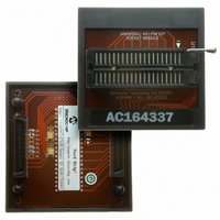
Manufacturer Part Number
AC164337
Description
MODULE SOCKET FOR PM3 40DIP
Manufacturer
Microchip Technology
Datasheet
1.AC164335.pdf
(286 pages)
Specifications of AC164337
Module/board Type
Socket Module - DIP
Product
Microcontroller Accessories
Lead Free Status / RoHS Status
Not applicable / Not applicable
For Use With/related Products
MPLAB® PM3
Lead Free Status / RoHS Status
Lead free / RoHS Compliant, Not applicable / Not applicable


dsPIC30F1010/202X
12.4.4
Multi-Phase PWM, as shown in Figure 12-6, uses
phase-shift values in the Phase registers to shift the
PWM outputs relative to the primary time base.
Because the phase-shift values are added to the pri-
mary time base, the phase-shifted outputs occur earlier
than a PWM channel that specifies zero phase shift. In
Multi-Phase mode, the specified phase shift is fixed by
the application’s design.
FIGURE 12-6:
12.4.5
Figure 12-7 shows the waveforms for Variable Phase-
Shift PWM. Power-converter circuits constantly change
the phase shift among PWM channels as a means to
control the flow of power, in contrast to most PWM cir-
cuits that vary the duty cycle of PWM signals to control
power flow. Often, in variable phase applications, the
PWM duty cycle is maintained at 50%. The phase-shift
value should be updated when the PWM signal is not
asserted. Complementary outputs are available in Vari-
able Phase-Shift mode.
FIGURE 12-7:
DS70178C-page 122
PWM1H
PWM2H
PWM4H
PWM3H
PWM2H
PWM1H
Phase2 (old value)
Duty Cycle
MULTI-PHASE PWM MODE
VARIABLE PHASE PWM MODE
Duty Cycle
Duty Cycle
Phase4
Duty Cycle
Phase3
MULTI-PHASE PWM
VARIABLE PHASE PWM
Period
Phase2
Duty Cycle
Period
PTMR=0
Phase2 (new value)
Duty Cycle
Duty Cycle
Duty Cycle
Preliminary
12.4.6
Figure 12-8
mode. This mode truncates the asserted PWM signal
when the selected external Fault signal is asserted.
The PWM output values are specified by the Fault
override bits (FLTDAT<1:0>) in the IOCONx register.
The override output remains in effect until the begin-
ning of the next PWM cycle. This mode is sometimes
used in Power Factor Correction (PFC) circuits where
the inductor current controls the PWM on time. This is
a constant frequency PWM mode.
FIGURE 12-8:
Period
Value
Duty
Cycle
PWMH
PWMH
0
FLTx Negates PWM
Timer
Value
CURRENT-LIMIT PWM MODE
Duty Cycle
Programmed
Duty Cycle
Actual
shows
CYCLE-BY-CYCLE
CURRENT-LIMIT PWM
MODE
Cycle-by-Cycle
© 2006 Microchip Technology Inc.
FLTx Negates PWM
Programmed
Duty Cycle
Duty Cycle
Actual
Current-Limit
Related parts for AC164337
Image
Part Number
Description
Manufacturer
Datasheet
Request
R

Part Number:
Description:
Manufacturer:
Microchip Technology Inc.
Datasheet:
Part Number:
Description:
Manufacturer:
Microchip Technology Inc.
Datasheet:
Part Number:
Description:
Manufacturer:
Microchip Technology Inc.
Datasheet:
Part Number:
Description:
Manufacturer:
Microchip Technology Inc.
Datasheet:
Part Number:
Description:
Manufacturer:
Microchip Technology Inc.
Datasheet:
Part Number:
Description:
Manufacturer:
Microchip Technology Inc.
Datasheet:
Part Number:
Description:
Manufacturer:
Microchip Technology Inc.
Datasheet:
Part Number:
Description:
Manufacturer:
Microchip Technology Inc.
Datasheet: