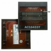
AC164337 Microchip Technology, AC164337 Datasheet - Page 283

AC164337
Manufacturer Part Number
AC164337
Description
MODULE SOCKET FOR PM3 40DIP
Manufacturer
Microchip Technology
Datasheet
1.AC164335.pdf
(286 pages)
Specifications of AC164337
Module/board Type
Socket Module - DIP
Product
Microcontroller Accessories
Lead Free Status / RoHS Status
Not applicable / Not applicable
For Use With/related Products
MPLAB® PM3
Lead Free Status / RoHS Status
Lead free / RoHS Compliant, Not applicable / Not applicable
- Current page: 283 of 286
- Download datasheet (5Mb)
Timing Characteristics
Timing Diagrams
Timing Diagrams and Specifications
Timing Diagrams.See Timing Characteristics
Timing Requirements
Timing Specifications
Traps
© 2006 Microchip Technology Inc.
A/D Conversion
Band Gap Start-up Time ........................................... 248
CLKO and I/O ........................................................... 245
External Clock........................................................... 240
I
I
Input Capture (CAPX) ............................................... 251
Motor Control PWM Module...................................... 253
Motor Control PWM Module Falult............................ 253
OC/PWM Module ...................................................... 252
Oscillator Start-up Timer ........................................... 246
Output Compare Module........................................... 251
Power-up Timer ........................................................ 246
Reset......................................................................... 246
SPI Module
Type A, B and C Timer External Clock ..................... 249
Watchdog Timer........................................................ 246
PWM Output ............................................................. 104
Time-out Sequence on Power-up (MCLR
Time-out Sequence on Power-up (MCLR
Time-out Sequence on Power-up (MCLR Tied
DC Characteristics - Internal RC Accuracy............... 242
Band Gap Start-up Time ........................................... 248
Brown-out Reset ....................................................... 247
CLKO and I/O ........................................................... 245
External Clock........................................................... 241
I
I
Input Capture ............................................................ 251
Motor Control PWM Module...................................... 253
Oscillator Start-up Timer ........................................... 247
Output Compare Module........................................... 251
Power-up Timer ........................................................ 247
Reset......................................................................... 247
Simple OC/PWM Mode............................................. 252
SPI Module
Type A Timer External Clock .................................... 249
Type B Timer External Clock .................................... 250
Type C Timer External Clock .................................... 250
Watchdog Timer........................................................ 247
PLL Clock.................................................................. 242
Trap Sources .............................................................. 49
2
2
2
2
C Bus Data
C Bus Start/Stop Bits
C Bus Data (Master Mode)..................................... 260
C Bus Data (Slave Mode)....................................... 262
10-Bit High-speed (CHPS = 01,
Master Mode ..................................................... 259
Slave Mode ....................................................... 261
Master Mode ..................................................... 259
Slave Mode ....................................................... 261
Master Mode (CKE = 0) .................................... 254
Master Mode (CKE = 1) .................................... 255
Slave Mode (CKE = 0) ...................................... 256
Slave Mode (CKE = 1) ...................................... 257
Not Tied to V
Not Tied to V
to V
Master Mode (CKE = 0) .................................... 254
Master Mode (CKE = 1) .................................... 255
Slave Mode (CKE = 0) ...................................... 256
Slave Mode (CKE = 1) ...................................... 258
DD
SIMSAM = 0, ASAM = 0, SSRC = 000) .... 264
) .............................................................. 211
DD
DD
), Case 1 .................................. 211
), Case 2 .................................. 212
Preliminary
U
UART
UART1 Mode Register (U1MODE)................................... 164
UART1 Register Map........................................................ 168
UART1 Status and Control Register (U1STA).................. 166
Unit ID Locations .............................................................. 197
Universal Asynchronous Receiver Transmitter. See UART
W
Wake-up from Sleep ......................................................... 197
Wake-up from Sleep and Idle ............................................. 51
Watchdog Timer
Watchdog Timer (WDT)............................................ 197, 214
WWW Address ................................................................. 273
WWW, On-Line Support ....................................................... 8
dsPIC30F1010/202X
Baud Rate Generator (BRG) .................................... 162
Enabling and Setting Up UART ................................ 162
IrDA
Receiving
Transmitting
Timing Characteristics .............................................. 246
Timing Requirements ............................................... 247
Enabling and Disabling............................................. 214
Operation.................................................................. 214
Built-in Encoder and Decoder........................... 163
8-bit or 9-bit Data Mode.................................... 163
8-bit Data Mode ................................................ 163
9-bit Data Mode ................................................ 163
Break and Sync Sequence ............................... 163
DS70178C-page 281
Related parts for AC164337
Image
Part Number
Description
Manufacturer
Datasheet
Request
R

Part Number:
Description:
Manufacturer:
Microchip Technology Inc.
Datasheet:

Part Number:
Description:
Manufacturer:
Microchip Technology Inc.
Datasheet:

Part Number:
Description:
Manufacturer:
Microchip Technology Inc.
Datasheet:

Part Number:
Description:
Manufacturer:
Microchip Technology Inc.
Datasheet:

Part Number:
Description:
Manufacturer:
Microchip Technology Inc.
Datasheet:

Part Number:
Description:
Manufacturer:
Microchip Technology Inc.
Datasheet:

Part Number:
Description:
Manufacturer:
Microchip Technology Inc.
Datasheet:

Part Number:
Description:
Manufacturer:
Microchip Technology Inc.
Datasheet:


