DM163025 Microchip Technology, DM163025 Datasheet - Page 13
DM163025
Manufacturer Part Number
DM163025
Description
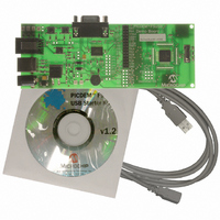
PIC DEM FULL SPEED USB DEMO BRD
Manufacturer
Microchip Technology
Specifications of DM163025
Main Purpose
Interface, USB 2.0 Host/Controller
Embedded
Yes, MCU, 8-Bit
Utilized Ic / Part
PIC18F2455/2550/4455/4550
Primary Attributes
Full Speed (12Mbps)
Secondary Attributes
MPLAB ICE 2000/4000 Emulator Interface, Temp Sensor, Expansion and PICtail Headers
Processor To Be Evaluated
PIC18F4550
Interface Type
RS-232, USB
Silicon Manufacturer
Microchip
Core Architecture
PIC
Core Sub-architecture
PIC18
Silicon Core Number
PIC18F
Silicon Family Name
PIC18F4xxx
Kit Contents
Demo Board, Cables, CD & Documents
Rohs Compliant
Yes
Lead Free Status / RoHS Status
Lead free / RoHS Compliant
Lead Free Status / RoHS Status
Lead free / RoHS Compliant, Lead free / RoHS Compliant
Other names
Q2086254
Available stocks
Company
Part Number
Manufacturer
Quantity
Price
Company:

Part Number:
DM163025
Manufacturer:
Microchip Technology
Quantity:
135
Company:
Part Number:
DM163025-1
Manufacturer:
MICROCHIP
Quantity:
12 000


© 2008 Microchip Technology Inc.
3. Oscillator: The demonstration board uses a 20 MHz crystal oscillator (Y1) as
4. ICD Configuration Jumpers: These three unpopulated jumper positions allow
5. Expansion and PICtail Daughter Board Headers: The pads at J6 and J7 are
6. Configuration Jumpers: A total of 13 unpopulated jumper positions are
7. Potentiometer: The potentiometer (R20) simulates an analog input for the
8. Temperature Sensor: A Microchip TC77 digital temperature sensor (U4)
9. Power LEDs (Green): These light to show that power is being supplied to the
10. Reset Pushbutton: This switch (S1) is tied to the MCLR pin of the PIC18F4550
11. Power Connector: Power (9 V
12. USB Connector: This is a standard USB series “B” receptacle. The USB port is
13. ICD Connector: This 6-wire RJ11 connector provides the standard interface
14. Status LED Bank: A bank of four green LEDs is used to show the operational
15. User-Defined Pushbuttons: These two switches (S2 and S3) are provided to
16. RS-232 (DB9F) Port: A standard D-shell connector, along with a standard level
the primary clock service. The PIC18F4550 uses this oscillator to generate the
necessary clock signals for both the USB Serial Interface Engine (SIE) and the
core processor.
the user to choose either legacy or dedicated ICSP™ and ICD ports for the
controller. By default, the board is hard-configured for the legacy port. The
configuration and use of these jumpers is detailed in Section 5.2.4 “Adding
In-Circuit Emulation Capability”.
provided for users to install the header and directly access the microcontroller’s
I/O port signals. In addition, the 14 even numbered pins of J6 (those on the right
side as viewed from the top) serve as the interface for Microchip’s PICtail
daughter boards. This allows the PICDEM FS USB board to be used as a test
platform and USB communications interface for the PICtail daughter boards.
provided across the board; these allow users to modify the board by configuring
its hardware to suit their needs. By default, all jumpers are bridged and all
features are enabled. The configuration and use of these jumpers is detailed in
Section 5.2 “Configuring the Demonstration Board Options”.
controller. Its real-time value can also displayed by the Demo Tool host software.
continuously monitors the board’s ambient temperature. Data is transmitted to
the controller via a 3-wire SPI interface, and is displayed in real time by the Demo
Tool software.
board, and to indicate how the board is being powered. LED D7 indicates that
the board is being powered from the bus, while D8 indicates the board is being
powered from a separate power supply.
controller; pressing it causes a hard device Reset.
power adapter through a mini barrel jack. Using an external supply is optional,
as all examples provided with the demonstration board can use power from the
USB cable.
the primary channel for controlling and communicating with the demonstration
board.
used by Microchip development and demonstration boards for programming and
debugging applications, using MPLAB ICD 2 and other development tools.
status of the board. Two LEDs (D1 and D2) are used by the application firmware
to indicate the status of the USB connection. The other LEDs (D3 and D4) can be
defined by the user; they are directly controllable through the Demo Tool software.
simulate digital control inputs. Pressing either button causes its port to read
as ‘0’.
shifter (U1), provides an RS-232 serial connection to the demonstration board.
DC
) can be supplied to the board from an external
DS51526B-page 9
Related parts for DM163025
Image
Part Number
Description
Manufacturer
Datasheet
Request
R

Part Number:
Description:
Manufacturer:
Microchip Technology Inc.
Datasheet:
Part Number:
Description:
Manufacturer:
Microchip Technology Inc.
Datasheet:
Part Number:
Description:
Manufacturer:
Microchip Technology Inc.
Datasheet:
Part Number:
Description:
Manufacturer:
Microchip Technology Inc.
Datasheet:
Part Number:
Description:
Manufacturer:
Microchip Technology Inc.
Datasheet:
Part Number:
Description:
Manufacturer:
Microchip Technology Inc.
Datasheet:
Part Number:
Description:
Manufacturer:
Microchip Technology Inc.
Datasheet:
Part Number:
Description:
Manufacturer:
Microchip Technology Inc.
Datasheet: