DM163025 Microchip Technology, DM163025 Datasheet - Page 37
DM163025
Manufacturer Part Number
DM163025
Description
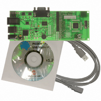
PIC DEM FULL SPEED USB DEMO BRD
Manufacturer
Microchip Technology
Specifications of DM163025
Main Purpose
Interface, USB 2.0 Host/Controller
Embedded
Yes, MCU, 8-Bit
Utilized Ic / Part
PIC18F2455/2550/4455/4550
Primary Attributes
Full Speed (12Mbps)
Secondary Attributes
MPLAB ICE 2000/4000 Emulator Interface, Temp Sensor, Expansion and PICtail Headers
Processor To Be Evaluated
PIC18F4550
Interface Type
RS-232, USB
Silicon Manufacturer
Microchip
Core Architecture
PIC
Core Sub-architecture
PIC18
Silicon Core Number
PIC18F
Silicon Family Name
PIC18F4xxx
Kit Contents
Demo Board, Cables, CD & Documents
Rohs Compliant
Yes
Lead Free Status / RoHS Status
Lead free / RoHS Compliant
Lead Free Status / RoHS Status
Lead free / RoHS Compliant, Lead free / RoHS Compliant
Other names
Q2086254
Available stocks
Company
Part Number
Manufacturer
Quantity
Price
Company:

Part Number:
DM163025
Manufacturer:
Microchip Technology
Quantity:
135
Company:
Part Number:
DM163025-1
Manufacturer:
MICROCHIP
Quantity:
12 000


© 2008 Microchip Technology Inc.
5.2.2
For the TC77 temperature sensor, each of the three lines that it uses to communicate
with the controller are bridged with a separate jumper. Removing all three jumpers
(JP10, JP11 and JP12) disables the sensor’s function, and makes all three controller
ports available to the user.
5.2.3
Using the MPLAB IDE and MPLAB ICD 2, users can reprogram the board’s
microcontroller using In-Circuit Serial Programming™ (ICSP™), and debug firmware
code using In-Circuit Debugger. The RJ-11 receptacle (J3), also known as the
ICSP/ICD connector, is the standard MPLAB ICD 2 interface found on most Microchip
development boards.
Most PIC18 microcontrollers only have one legacy ICSP/ICD port, which shares I/O
pins RB6 and RB7. When used, the legacy port prevents applications from using these
pins as normal I/O ports. The 44-pin TQFP version of the PIC18F4550 is the only vari-
ant of the full-speed USB family of devices to have a second ICSP/ICD port on pins not
used for I/O. This dedicated port allows RB6 and RB7 to be utilized by the user’s
application.
The PICDEM FS USB board can be configured to work with either the legacy or dedi-
cated port by using jumpers, JP14 through JP16. As shipped, the demonstration board
is hardware-configured for the legacy port. To change this, the user must cut the traces
indicated in Figure 5-1 (item 14), and install pins and box jumpers. When installed, the
ICD connector is configured by the jumpers as shown in Table 5-2.
In addition to setting the jumpers, the ICPRT Configuration bit in CONFIG4L must also
be properly set. To enable the dedicated ICSP/ICD port, ICPRT must be set (= 1).
When the board is configured to use the dedicated ICSP/ICD port, the Reset switch,
S1, will no longer function. The ICRST pin acts only as an active-high Reset port, which
works when the MPLAB ICD 2 sends a high-voltage programming signal, (V
MCLR pin acts as both active-low and active-high Reset ports. Thus, the Reset switch,
S1, only works when connected to the MCLR pin.
Additional information regarding the dedicated ICSP/ICD port can be found in the
“Special Features” section of the device data sheet (DS39632).
TABLE 5-2:
Legacy ICD (CHP_MCLR/RB7/RB6)
Dedicated Port (ICRST/ICPGD/ICPGC)
Note 1:
2:
Disabling the Temperature Sensor
ICSP/ICD Configuration
ICD Connector Configuration
For JP14 through JP16, pin 1 is the location closest to the microcontroller.
Before using the ICD connector for programming or debugging, verify
that all three jumpers are set correctly. Failure to do so may result in
programming or debugger failure.
JUMPER CONFIGURATION FOR THE ICSP™/ICD CONNECTOR
Pins 1-2
Pins 2-3
JP14
Pins 1-2
Pins 2-3
JP15
DS51526B-page 33
IHH
Pins 1-2
Pins 2-3
J16
). The
Related parts for DM163025
Image
Part Number
Description
Manufacturer
Datasheet
Request
R

Part Number:
Description:
Manufacturer:
Microchip Technology Inc.
Datasheet:
Part Number:
Description:
Manufacturer:
Microchip Technology Inc.
Datasheet:
Part Number:
Description:
Manufacturer:
Microchip Technology Inc.
Datasheet:
Part Number:
Description:
Manufacturer:
Microchip Technology Inc.
Datasheet:
Part Number:
Description:
Manufacturer:
Microchip Technology Inc.
Datasheet:
Part Number:
Description:
Manufacturer:
Microchip Technology Inc.
Datasheet:
Part Number:
Description:
Manufacturer:
Microchip Technology Inc.
Datasheet:
Part Number:
Description:
Manufacturer:
Microchip Technology Inc.
Datasheet: