DM163025 Microchip Technology, DM163025 Datasheet - Page 26
DM163025
Manufacturer Part Number
DM163025
Description
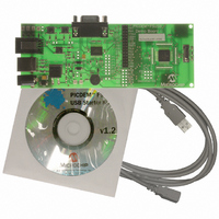
PIC DEM FULL SPEED USB DEMO BRD
Manufacturer
Microchip Technology
Specifications of DM163025
Main Purpose
Interface, USB 2.0 Host/Controller
Embedded
Yes, MCU, 8-Bit
Utilized Ic / Part
PIC18F2455/2550/4455/4550
Primary Attributes
Full Speed (12Mbps)
Secondary Attributes
MPLAB ICE 2000/4000 Emulator Interface, Temp Sensor, Expansion and PICtail Headers
Processor To Be Evaluated
PIC18F4550
Interface Type
RS-232, USB
Silicon Manufacturer
Microchip
Core Architecture
PIC
Core Sub-architecture
PIC18
Silicon Core Number
PIC18F
Silicon Family Name
PIC18F4xxx
Kit Contents
Demo Board, Cables, CD & Documents
Rohs Compliant
Yes
Lead Free Status / RoHS Status
Lead free / RoHS Compliant
Lead Free Status / RoHS Status
Lead free / RoHS Compliant, Lead free / RoHS Compliant
Other names
Q2086254
Available stocks
Company
Part Number
Manufacturer
Quantity
Price
Company:

Part Number:
DM163025
Manufacturer:
Microchip Technology
Quantity:
135
Company:
Part Number:
DM163025-1
Manufacturer:
MICROCHIP
Quantity:
12 000


3.5
DS51526B-page 22
BOOTLOAD MODE
™
The Bootload mode provides a simple means of reprogramming the on-board
microcontroller without using an external programming device. The PICDEM FS USB
board is preprogrammed with a bootload program that allows designers to download
and test new code through the Demo Tool application.
This section describes the Bootload mode, as well as a brief overview of the architec-
ture of the bootload program. An understanding on how the bootload firmware coexists
with the user firmware is important in developing a successful end application.
3.5.1
To start using the application, press and hold S2 while resetting the board (pressing and
releasing S1). The entry condition on the PICDEM FS USB board and the provided
firmware is determined by the status of the switch button, S2, which is checked once
after each Reset. If the button is held down during a Reset, the microcontroller enters
the Bootload mode; otherwise, it starts executing user code from address 0x0800.
After the Reset, select “PICDEM FS USB 0 (Boot)” from the “Select PICDEM FS USB
Board” dropdown box. When the Demo Tool application successfully connects to the
board, the message “USB Bootload Firmware Version x.x” will appear on the left side
of the status bar at the bottom of the window.
3.5.2
Program Memory Usage
Figure 3-4 shows the memory map of the PIC18F4550. The first 2,048 bytes of pro-
gram memory are reserved as the boot block, which is utilized almost entirely for the
bootloader firmware. The bootloader is a self-contained program with its own USB
driver firmware, USB descriptor set, bootload command interpreter and bootload
function handlers. The USB driver firmware used with the bootloader is a modified
version of the Microchip USB firmware framework library, and incorporates a smaller
set of features and more static design.
The boot block can be write-protected to prevent accidental overwriting of the boot
program. The default setting from factory has the boot block write-protect option
enabled.
Remapped Vectors
Since the hardware Reset and interrupt vectors lie within the boot area and cannot be
edited if the block is write-protected, they are remapped through software to the
nearest parallel location outside the boot block: 0x0800 for Reset, 0x0808 for the
high-priority interrupt vector and 0x0818 for the low-priority interrupt vector. Remapping
is simply a GOTO instruction for interrupts. Users should note that an additional latency
of two instruction cycles is required to handle interrupts.
Note:
Bootload Mode Entry
Memory Organization
Even if the Demo Tool application is running in Bootload mode, a simple
reset of the board (pressing S1) will not cause the board itself to enter
Bootload mode.
© 2008 Microchip Technology Inc.
Related parts for DM163025
Image
Part Number
Description
Manufacturer
Datasheet
Request
R

Part Number:
Description:
Manufacturer:
Microchip Technology Inc.
Datasheet:
Part Number:
Description:
Manufacturer:
Microchip Technology Inc.
Datasheet:
Part Number:
Description:
Manufacturer:
Microchip Technology Inc.
Datasheet:
Part Number:
Description:
Manufacturer:
Microchip Technology Inc.
Datasheet:
Part Number:
Description:
Manufacturer:
Microchip Technology Inc.
Datasheet:
Part Number:
Description:
Manufacturer:
Microchip Technology Inc.
Datasheet:
Part Number:
Description:
Manufacturer:
Microchip Technology Inc.
Datasheet:
Part Number:
Description:
Manufacturer:
Microchip Technology Inc.
Datasheet: