MCP6XXXDM-FLTR Microchip Technology, MCP6XXXDM-FLTR Datasheet
MCP6XXXDM-FLTR
Specifications of MCP6XXXDM-FLTR
Available stocks


Related parts for MCP6XXXDM-FLTR

MCP6XXXDM-FLTR Summary of contents
Page 1
... Active Filter Demo Board Kit © 2006 Microchip Technology Inc. User’s Guide DS51614A ...
Page 2
... PowerMate, PowerTool, REAL ICE, rfLAB, rfPICDEM, Select Mode, Smart Serial, SmartTel, Total Endurance, UNI/O, WiperLock and ZENA are trademarks of Microchip Technology Incorporated in the U.S.A. and other countries. SQTP is a service mark of Microchip Technology Incorporated in the U.S.A. All other trademarks mentioned herein are property of their respective companies. ...
Page 3
... Power Supplies ............................................................................................ 25 4.3 Filter Section Ordering for Noise and Headroom ......................................... 27 4.4 Combining Low-pass and High-pass Sections ............................................. 27 4.5 Higher Frequency Filters .............................................................................. 27 4.6 Using 8-Pin SOIC Op Amps ......................................................................... 28 © 2006 Microchip Technology Inc. ACTIVE FILTER DEMO BOARD KIT Table of Contents USER’S GUIDE DS51614A-page iii ...
Page 4
... Filter Section (Sub-Assembly #: 102-00098R1) ................................ 31 DD A.3 Active Filter Section (Sub-Assembly #: 102-00097R1) ................................ 34 A.4 Accessory Bag (Sub-Assembly #: 110-00097R1) ........................................ 37 Appendix B. Bill Of Materials (BOM) ..........................................................................39 B Filter Section BOMs .......................................................................... 39 DD B.2 Active Filter Section BOM ............................................................................ 40 B.3 Accessory Bag BOM .................................................................................... 41 Worldwide Sales and Service .....................................................................................42 DS51614A-page iv © 2006 Microchip Technology Inc. ...
Page 5
... Active Filter Demo Board Kit. • Appendix B. “Bill Of Materials (BOM)” – Lists the parts used to build the sub-assemblies in the Active Filter Demo Board Kit. © 2006 Microchip Technology Inc. ACTIVE FILTER DEMO BOARD KIT Preface NOTICE TO CUSTOMERS USER’ ...
Page 6
... Optional arguments mcc18 [options] file [options] Choice of mutually exclusive errorlevel {0|1} arguments selection Replaces repeated text var_name [, var_name...] Represents code supplied by void main (void) user { ... } © 2006 Microchip Technology Inc. Examples ® IDE User’s Guide ...
Page 7
... Local sales offices are also available to help customers. A listing of sales offices and locations is included in the back of this document. Technical support is available through the web site at: http://support.microchip.com DOCUMENT REVISION HISTORY Revision A (June 2006) • Initial Release of this Document. © 2006 Microchip Technology Inc. DS51614A-page 3 ...
Page 8
... NOTES: DS51614A-page 4 © 2006 Microchip Technology Inc. ...
Page 9
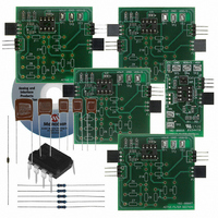
... INTRODUCTION The Active Filter Demo Board Kit is described by the following: • Assembly # : 114-00097R1 • Order # : MCP6XXXDM-FLTR • Name: Active Filter Demo Board Kit Items discussed in this chapter include: • Kit Contents • Intended Use of the Active Filter Demo Board Kit • ...
Page 10
... Four PCBs designed to be cascaded - Support filter orders between and Provide output test points for lab equipment • Accessory Bag - Sub-Assembly # : 110-00097R1 - Kit of resistors, capacitors, and op amps that can be used to build the filter circuit in Figure 2-8 DS51614A-page 6 ® V2.0 (see © 2006 Microchip Technology Inc. ...
Page 11
... DD Filter Section 2 Signal Generator FIGURE 1-2: Figure 1-3 shows the block diagram of the V the block diagram of the Active Filter Sections. Supply FIGURE 1-3: Power Supply Input Signal Input FIGURE 1-4: © 2006 Microchip Technology Inc Active Active Filter Filter Section Section Measurement Setup Block Diagram ...
Page 12
... SPICE listing for further simulations. Users can select a low-pass, band-pass or high-pass response. Available functions are Bessel, Butterworth, and Chebyshev, with order between and 8. DS51614A-page innovative software tool that simplifies active (op amp) filter design. © 2006 Microchip Technology Inc. ...
Page 13
... The (surface mount) test points allow lab equipment to be connected to these boards. The user provides the input signal and power to the V the output signal at the last Active Filter Section. Lab Power Supply Function Generator FIGURE 2-1: © 2006 Microchip Technology Inc. ACTIVE FILTER DEMO BOARD KIT Active Filter Section V /2 Filter Section DD Board Connections for the Active Filter Demo Board Kit. USER’ ...
Page 14
... C 3 0.1 µ kΩ 0.1 µF 20 kΩ GND V /2 Filter Section Circuit (INT on bottom) /2 line on all of the PCBs DD /2 (EXT on top, as shown) at EXT), or internally ( EXT INT GND GND U 1 MCP6271 GND 4 V OUT GND P 2 © 2006 Microchip Technology Inc. 1 ...
Page 15
... Active Filter Demo Board Kit. Figure 2-4 shows the circuit diagram for the Active Filter Section GND GND V IN GND FIGURE 2-4: © 2006 Microchip Technology Inc GND GND V IN GND V /2 Filter Section Top View. ...
Page 16
... The socket pairs are labeled Z1 through Z12 • The following sub-sections detail how the resistors and capacitors are chosen and populated GND GND V IN GND FIGURE 2-5: DS51614A-page 12 Active Filter Section Top View GND GND V OUT GND © 2006 Microchip Technology Inc. ...
Page 17
... The different circuit topologies referred to in Section 2.5.2 “Sallen-Key, Low-pass Fil- ter Sections”, Section 2.5.3 “Sallen-Key, High-pass Filter Sections”, and Section 2.5.4 “Multiple Feedback, Low-pass and Band-pass Filter Sections” will be labeled as shown in Figure 2-6. FIGURE 2-6: © 2006 Microchip Technology Inc. /2 Filter Section DD AAA-BB#-C AAA: ...
Page 18
... Sallen-Key, Low-pass (modified) Filter Topologies. SK-LP1-K SK-LP2-K 0Ω R11 R11 R12 — C11 — — C11 C12 — — 0Ω 0Ω — — — — SK-LP2 C11 V DD R11 R12 OUT C12 SK-LP2-K C11 V DD R11 R12 OUT C12 © 2006 Microchip Technology Inc. ...
Page 19
... C11 V IN R11 C11 V IN R11 FIGURE 2-8: © 2006 Microchip Technology Inc. IMPEDANCES FOR SALLEN-KEY, HIGH-PASS FILTER SECTIONS SK-HP1 SK-HP2 0Ω C11 C11 C12 — R11 R11 R12 — — — — — — — — — — — — ...
Page 20
... R11 R11 — R12 C12 — R12 C11 R13 C12 C11 R13 MFB-LP2 R12 C11 V DD R11 R13 OUT C12 MFB-BP2 R13 V DD C12 OUT R12 © 2006 Microchip Technology Inc. ...
Page 21
... Section 3.2 “The Filter Design” and Section 3.3 “Putting the Filter Together”). 2. Verify the power supply voltages, including V 3. Test the filter response as described in Section 3.4 “Testing the Filter”. © 2006 Microchip Technology Inc. /2, for all of the boards. DD DS51614A-page 17 ...
Page 22
... NOTES: DS51614A-page 18 © 2006 Microchip Technology Inc. ...
Page 23
... Notice how close the measured and simulated data are; this happened because the MCP601 op amp is much faster than the filter, and because 1% resistors and 5% capacitors were used. © 2006 Microchip Technology Inc. ACTIVE FILTER DEMO BOARD KIT SK-LP2 C21 0.39µ ...
Page 24
... Filter Frequency Response. th order, there are no components for Section # 4. ACCESSORY BAG PARTS LIST Qty Section Measured 1,000 Reference PCB Label C11 Z5 C22 Z5 C32 Z5 C31 Z3 C21 Z3 — Z1, Z11 — Z11 — Z11 R21 Z1 R31 Z1 R22 Z2 R11 Z2 R32 © 2006 Microchip Technology Inc. ...
Page 25
... Figure 3-6 shows a histogram of the pass-band frequency (f same simulation. © 2006 Microchip Technology Inc. /2 Filter Section) provides an easy way to connect the input signal DD Picture of the Filter Supported by the Active Filter Demo Board ...
Page 26
... Frequency (Hz) Gain Error (Monte Carlo simulation) vs. Frequency. 26% 100 MC Sims 24% 1% R's 22% 20% 5% C's 18% 16% 14% 12% 10 Pass-Band Frequency at -3.01 dB (Hz) Pass-Band Frequency (Monte Carlo simulation) Histogram. 1,000 © 2006 Microchip Technology Inc. ...
Page 27
... Many SPICE simulators support Monte Carlo simulations. Using this capability on your design will help determine what tolerances are needed on your design. The same results can be obtained by measuring many filters (i.e 10,000), but at a greater cost. © 2006 Microchip Technology Inc. 0 -10 -20 ...
Page 28
... NOTES: DS51614A-page 24 © 2006 Microchip Technology Inc. ...
Page 29
... Voltage GND to the V - Voltage –V Set JP1 to External (EXT) These signals correspond to the pins of the unpopulated P1 and J1 FIGURE 4-1: © 2006 Microchip Technology Inc. ACTIVE FILTER DEMO BOARD KIT /2 Filter Section (see Figure 4-1) setup (EXT, as shown the board’s V input (TP3) ...
Page 30
... DS51614A-page 26 Do not connect ground probe to GND Setting up Active Filter Section” or dual supplies. Oscilloscope V GND OUT GND GND V OUT GND will be S © 2006 Microchip Technology Inc. ...
Page 31
... All time parameters are multiplied by the same power of 10 For example, a low-pass filter with a pass-bandfrequency of 1 MHz could be scaled back to 10 kHz. The final design must be evaluated on a board capable of supporting higher frequency signals. © 2006 Microchip Technology Inc. ) are ordered from lowest to highest (from > ...
Page 32
... Board. Figure 4-4 shows a SOIC-8 op amp and a DIP-8 socket, soldered onto the 8-Pin SOIC/MSOP/TSSOP/DIP Evaluation Board available from Microchip Technology Inc (order # SOIC8EV). The two interconnect strips on the bottom are Samtec part # BBS-14-T-B or equivalent and are soldered into the through holes for the DIP-8 socket. ...
Page 33
... FIGURE 4-5: © 2006 Microchip Technology Inc. Connecting Adaptor Board onto Active Filter Section. DS51614A-page 29 ...
Page 34
... NOTES: DS51614A-page 30 © 2006 Microchip Technology Inc. ...
Page 35
... JP1 allows the user to choose the V • A lab supply (EXT = External V • Op amp U1’s output (INT = Internal V See Section B.1 “V © 2006 Microchip Technology Inc. ACTIVE FILTER DEMO BOARD KIT /2 Filter Section circuit diagram. The input and output DD /2 reference voltage. The op amp U1 buffers this DD ...
Page 36
... FIGURE A- Filter Section – Schematic. DD DS51614A-page 32 © 2006 Microchip Technology Inc. ...
Page 37
... Board Plots The Gerber files for this board are available on the Microchip website (www.microchip.com) and are contained in the zip file “00098R1 Gerbers.zip”. FIGURE A-2: FIGURE A-3: © 2006 Microchip Technology Inc Filter Section – Top Silk Screen Filter Section – Top Metal Layer. ...
Page 38
... See Section B.1 “V DS51614A-page Filter Section – Bottom Metal Layer Filter Sections circuit diagram. The input and output bypass capacitor for Filter Section BOMs” for the Bill of Material for this kit. DD /2, and R1 DD © 2006 Microchip Technology Inc. ...
Page 39
... FIGURE A-5: Active Filter Section – Schematic. © 2006 Microchip Technology Inc. DS51614A-page 35 ...
Page 40
... The Gerber files for this board are available on the Microchip website (www.microchip.com) and are contained in the zip file “00097R1 Gerbers.zip”. FIGURE A-6: FIGURE A-7: DS51614A-page 36 Active Filter Section – Top Silk-Screen. Active Filter Section – Top Metal Layer. © 2006 Microchip Technology Inc. ...
Page 41
... MCP6271 op amps than needed for Figure 3-1; there are enough to populate all of the DIP-8 sockets in the Active Filter Demo Board Kit. These op amps are included in the accessory bag for ESD protection. © 2006 Microchip Technology Inc. Active Filter Section – Bottom Metal Layer. = 100 Hz, and Gain = 1 V/V. It uses single supply, ...
Page 42
... NOTES: DS51614A-page 38 © 2006 Microchip Technology Inc. ...
Page 43
... Op amps in SOIC-8 package are supplied by the user, if desired. See ”4.6 “Using 8-Pin SOIC Op Amps” for information on using op amps in these packages (150 mil wide). © 2006 Microchip Technology Inc. ACTIVE FILTER DEMO BOARD KIT BILL OF MATERIALS (102-00098R1) Description 100 nF, 50V, 10%, X7R, 0805 SMD, Ceramic 1.0 µ ...
Page 44
... BILL OF MATERIALS – UNPOPULATED PARTS (102-00097R1) Description Part Number C0805C104K5RACTU C0805C105K4RACTU 640453-3 ® 801-44-003-20-001000 RC0805FR-0710RL 5016 2-641260-1 ® 0252-0-15-15-30-27-10-0 104-00097R1 Manufacturer Part Number Microchip MCP6271-E/P Technology Inc Microchip MCP6271-E/SN Technology Inc — — are provided by the 1 11 © 2006 Microchip Technology Inc. ...
Page 45
... These five op amps are placed in ESD protective “clam shells,” which are then put into an ESD protective bag with the resistors and capacitors. © 2006 Microchip Technology Inc. BILL OF MATERIALS (110-00097R1) Description 100 nF, 50V, 5%, Radial, Polyester Film ...
Page 46
... Fax: 886-3-572-6459 Taiwan - Kaohsiung Tel: 886-7-536-4818 Fax: 886-7-536-4803 Taiwan - Taipei Tel: 886-2-2500-6610 Fax: 886-2-2508-0102 Thailand - Bangkok Tel: 66-2-694-1351 Fax: 66-2-694-1350 © 2006 Microchip Technology Inc. EUROPE Austria - Wels Tel: 43-7242-2244-3910 Fax: 43-7242-2244-393 Denmark - Copenhagen Tel: 45-4450-2828 Fax: 45-4485-2829 France - Paris Tel: 33-1-69-53-63-20 ...