MCP6XXXDM-FLTR Microchip Technology, MCP6XXXDM-FLTR Datasheet - Page 38
MCP6XXXDM-FLTR
Manufacturer Part Number
MCP6XXXDM-FLTR
Description
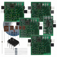
KIT DEMO BOARD ACTIVE FILTER
Manufacturer
Microchip Technology
Datasheet
1.MCP6XXXDM-FLTR.pdf
(46 pages)
Specifications of MCP6XXXDM-FLTR
Main Purpose
Filters, Active - Bandpass, Highpass, Lowpass
Embedded
Yes, MCU, 8-Bit
Utilized Ic / Part
MCP6271
Primary Attributes
Cascadable PCBs, Single Supply
Secondary Attributes
Bessel, Butterworth, and Chebyshev, with Order 1 ~ 8
Processor To Be Evaluated
MCP6271
Lead Free Status / RoHS Status
Not applicable / Not applicable
Lead Free Status / RoHS Status
Lead free / RoHS Compliant, Not applicable / Not applicable
Available stocks
Company
Part Number
Manufacturer
Quantity
Price
Company:

Part Number:
MCP6XXXDM-FLTR
Manufacturer:
MICROCHIP
Quantity:
12 000
Part Number:
MCP6XXXDM-FLTR
Manufacturer:
MICROCHIP/微芯
Quantity:
20 000


A.3
DS51614A-page 34
ACTIVE FILTER SECTION (SUB-ASSEMBLY #: 102-00097R1)
FIGURE A-4:
A.3.1
See Figure A-5 for the V
headers (J1, J2, P1, and P2) allow the PCBs to be cascaded as needed. The filter order
will determine how many of these boards need to be cascaded.
The impedances Z1 to Z11 are realized as resistors, capacitors, shorts or open circuits,
depending on the section topology. These components are placed in pin sockets.
Op amp U1 interacts with the impedances Z1 to Z11 to form an active filter section (one
or two pole). Op amp U1 is usually a single, PDIP-8 part inserted into the DIP-8 socket;
it can be a SOIC-8 that is soldered to the board (see U1A in Figure A-5).
C1 and C3 are bypass capacitors for V
is a snubber resistor that helps prevent capacitive loading problems for the op amp on
the V
The demonstration board includes test points for convenience on the bench. TP1
through TP3 make it possible to measure the output voltage of each filter section.
See Section B.1 “V
DD
/2 Filter Section.
Circuit
DD
V
DD
/2 Filter Section BOMs” for the Bill of Material for this kit.
DD
/2 Filter Section – Bottom Metal Layer.
/2 Filter Sections circuit diagram. The input and output
DD
. C2 is a bypass capacitor for V
© 2006 Microchip Technology Inc.
DD
/2, and R1
Related parts for MCP6XXXDM-FLTR
Image
Part Number
Description
Manufacturer
Datasheet
Request
R

Part Number:
Description:
Manufacturer:
Microchip Technology Inc.
Datasheet:
Part Number:
Description:
Manufacturer:
Microchip Technology Inc.
Datasheet:
Part Number:
Description:
Manufacturer:
Microchip Technology Inc.
Datasheet:
Part Number:
Description:
Manufacturer:
Microchip Technology Inc.
Datasheet:
Part Number:
Description:
Manufacturer:
Microchip Technology Inc.
Datasheet:
Part Number:
Description:
Manufacturer:
Microchip Technology Inc.
Datasheet:
Part Number:
Description:
Manufacturer:
Microchip Technology Inc.
Datasheet:
Part Number:
Description:
Manufacturer:
Microchip Technology Inc.
Datasheet: