AT89STK-05 Atmel, AT89STK-05 Datasheet - Page 6
AT89STK-05
Manufacturer Part Number
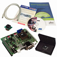
AT89STK-05
Description
KIT STARTER FOR AT89C5131
Manufacturer
Atmel
Specifications of AT89STK-05
Main Purpose
*
Embedded
*
Utilized Ic / Part
AT89C5131
Primary Attributes
*
Secondary Attributes
*
Processor To Be Evaluated
AT89C5131A
Interface Type
RS-232, USB
Lead Free Status / RoHS Status
Contains lead / RoHS non-compliant


4245A–USB–11/04
Hardware Description
2.2
2-4
Power Supply
The on-board power supply circuitry allows various power supply configurations.
The power source can be:
The voltage output can be the direct power source, regulated at 5V or 3.3V.
The power supply selection is performed using the JP2, JP3, JP4 and JP5 jumpers.
The power supply can be turned on/off using the “power” switch (SW6). Once the power
is established, the power LED (D9) is lit.
Figure 2-2. Different Power Configurations
Regulation
3.3V Regulate
5V Regulate
Direct Input
–
–
–
V
V
External power supply (from 6 to 12V) or 9V battery
Power
BUS
BUS
Source
from USB (5V)
from USB (5V) through the current limiter
VCC
VCC
VCC
VBUS
LIM
LIM
LIM
PWR.S.
PWR.S.
PWR.S.
PWR
PWR
PWR
3.3V
3.3V
3.3V
5V
5V
5V
REG
REG
REG
VCC
VCC
VCC
Current Limiter
VBUS and
LIM
LIM
LIM
PWR.S.
PWR.S.
PWR.S.
AT89C5131A Starter Kit Hardware User Guide
PWR
PWR
PWR
3.3V
3.3V
3.3V
5V
5V
5V
REG
REG
REG
VCC
VCC
VCC
External
LIM
LIM
LIM
PWR.S.
PWR.S.
PWR.S.
PWR
PWR
PWR
3.3V
3.3V
3.3V
5V
5V
5V
REG
REG
REG
Related parts for AT89STK-05
Image
Part Number
Description
Manufacturer
Datasheet
Request
R

Part Number:
Description:
KIT EVAL APPL MASS STORAGE
Manufacturer:
Atmel
Datasheet:

Part Number:
Description:
KIT DEMOBOARD 8051 MCU W/CAN
Manufacturer:
Atmel
Datasheet:

Part Number:
Description:
KIT STARTER FOR AT83C24
Manufacturer:
Atmel
Datasheet:

Part Number:
Description:
EVAL BOARD FOR AT83C26
Manufacturer:
Atmel
Datasheet:

Part Number:
Description:
KIT STARTER FOR MCU AT8XC5122/23
Manufacturer:
Atmel
Datasheet:

Part Number:
Description:
KIT STARTER FOR AT89C51RX2
Manufacturer:
Atmel
Datasheet:


Part Number:
Description:
8-Bit Microcontroller with 4K Bytes Flash
Manufacturer:
ATMEL Corporation
Datasheet:

Part Number:
Description:
DEV KIT FOR AVR/AVR32
Manufacturer:
Atmel
Datasheet:
Part Number:
Description:
INTERVAL AND WIPE/WASH WIPER CONTROL IC WITH DELAY
Manufacturer:
ATMEL Corporation
Datasheet:
Part Number:
Description:
Low-Voltage Voice-Switched IC for Hands-Free Operation
Manufacturer:
ATMEL Corporation
Datasheet:
Part Number:
Description:
MONOLITHIC INTEGRATED FEATUREPHONE CIRCUIT
Manufacturer:
ATMEL Corporation
Datasheet:
Part Number:
Description:
AM-FM Receiver IC U4255BM-M
Manufacturer:
ATMEL Corporation
Datasheet:
Part Number:
Description:
Monolithic Integrated Feature Phone Circuit
Manufacturer:
ATMEL Corporation
Datasheet: