ATAVRMC200 Atmel, ATAVRMC200 Datasheet
ATAVRMC200
Specifications of ATAVRMC200


Related parts for ATAVRMC200


ATAVRMC200 Summary of contents
Page 1
... ATAVRMC200 ......................................................................................................... Hardware User Guide ...
Page 2
... ATAVRMC200 Hardware "ATTENTION AND WARNING: The tools provided herein involve the use of high volt- age and may result in electrocution if improperly used. Atmel advises you to read through the entire documentation in order to understand the application and develop- ment tools prior to use. Atmel assume no liability and no responsibility for any injury as a result of these development tools ...
Page 3
... ATAVRMC200 Hardware User Guide Section 1 Introduction ........................................................................................... 1-1 1.1 Overview ...................................................................................................1-1 1.2 ATAVRMC200 Features ...........................................................................1-2 Section 2 Getting Started...................................................................................... 2-3 Section 3 Hardware Description ........................................................................... 3-4 3.1 Block Diagram...........................................................................................3-4 3.2 Power Supply ............................................................................................3-5 3.3 ISP / Debug wire Connector......................................................................3-6 3.4 Program Interaction...................................................................................3-7 3.5 Hardware Overheating Detection ...
Page 4
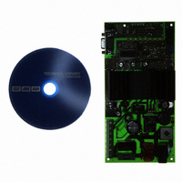
... ATAVRMC200 starter kit dedicated to AT90PWM3. The ATAVRMC200 is an evaluation kit dedicated to AC induction motor control, The kit includes an evaluation board, and demonstration software. It allows users to quickly evaluate the capability of the AT90PWM3 AVR® microcontroller to control a three phase asynchronous induction motor ...
Page 5
... ATAVRMC200 Features ATAVRMC200 Hardware User Guide The ATAVRMC200 provides the following features: AT90PWM3-16SQ SO32 device (2.7 - 5.5V) Power bridge for AC induction Motors (Maximum Power 370W) Embedded AC/DC power supply Hardware temperature detection Hardware overcurrent detection On-board Voltage Regulator (5V) AVR Studio® Software Interface(1) ...
Page 6
... ATAVRMC200 Hardware User Guide This chapter describes how to connect the AC motor on the MC200 board and run the embedded software. The PWM3 part is already programmed with a firmware allowing to run a three phase AC motor. Note: For 220V AC motor MC200 board must be powered with 220V AC, for 110V AC motor MC200 board must be powered with 110V AC ...
Page 7
... ATAVRMC200 Hardware User Guide Connect the power as describe below. Phase line connected to pin 3 (PH) of J1, Neutral Line connected to pin 2 (N) of J1and Earth connected to Pin (Ground). Switch power ON and enjoy the demo! 4 7638A–AVR–05/06 ...
Page 8
... Block Diagram Figure 3-1. ATAVRMC200 Block Diagram 110/230VAC AC/DC 48V DC (debug mode only) 15VDC Debug / ISP Debug Wire ISP Opto-isolated Isp ISP Com RS232 Sensor Interface ATAVRMC200 Hardware User Guide Hardware Description 5VDC Drivers AT90PWM3 Current and Temperature feed back Pushbuttons & ...
Page 9
... VBridge = 15V DC for drivers control. • and VDD = 5V DC for cpu power supply. LED1 is always lit when VBridge power is applied to ATAVRMC200. During microcode debugging phase, the user must power the board directly with VDC= 48V DC through J1 connector (PH and N connection), it will allow to check the signal on oscilloscope and use DebugWire interface (J3) to program and debug micro- code for AT90PWM3 part ...
Page 10
... ISP / Debug wire Connector ATAVRMC200 Hardware User Guide ATAVRMC200 has a six pin ISP connector (J3) allowing to reprogram the part with new code using standard AVR ISP tools. The same connector can be used as standard AVR debugWire connector Figure 3 ISP / DebugWire Connector Position Table 3-1 ...
Page 11
... Hardware Overheating Detection ATAVRMC200 Hardware User Guide To help programmers, the ATAVRMC200 board has two push buttons, one potentiome- ter and two leds available for user interactions. Figure 3-4 . Position of Available Interaction Features Table 3-2 . AT90PWM3 Pin number of Available Interaction Features ...
Page 12
... The ATAVRMC200 board has an opto isolated area (in grey below) allowing to connect the board to external link when the board is powered by 110/220V AC. The opto isolated uart (connector J7) is connected to Rxd and Txd pin of AT90PWM3, it allows full duplex communication ...
Page 13
... The ATAVRMC200 has three opto isolated inputs that can be used for sensors connec- tion. The connector J5 is dedicated to this inputs. By default opto isolated area must be powered using J4 connector, but if inputs signals have enought power to drive directly opto coupler, then power throught J5 is optional and if not used solder bridge must be closed on the board to bypass the PFET transistors associated to each inputs (refer to schematics) ...
Page 14
... ISP Opto Isolated ATAVRMC200 Hardware User Guide Table 3 pin number vs signal Pin number not use, reserved for future extension Signal VCC GND Input 2 Input 1 Input 0 11 7638A–AVR–05/06 ...
Page 15
... Test Points ATAVRMC200 Hardware User Guide The ATAVRMC200 board has test points for debug and engineering development. The following table summarises all test points, please refer to schematics for detailed informations Table 3-5 . Test Point vs signal name. Signal Name GND TP1 ...
Page 16
... ATAVRMC200 Hardware User Guide Figure 3-6 . ATAVRMC200 Test Points Position TP2/VDC TP3/VBRIDGE TP1/GND 13 7638A–AVR–05/06 ...
Page 17
... The AVR ISP (or JTAGICE mkII) programming interface is integrated in AVR Studio. To program the device using AVR ISP (or JTAGICE mkII) programmer, connect the 6- wire cable on the ISP connector of the ATAVRMC200 as shown in Figure 4-1. Note: See AVR Studio on-line Help for information. ...
Page 18
... ISP6PIN connector of the STK500 board and the ISP connector of the ATAVRMC200 as shown in Figure 4-2. The STK500 board delivers sufficient power to supply the AT90PWM3 of the ATAVRMC200 board not necessary to supply the ATAVRMC200 board when it is used with the STK500. Note: See AVR Studio on-line Help for information. ...
Page 19
... Programming using JTAGICE mkII ATAVRMC200 Hardware User Guide Figure 4-2 . Programming from STK500 The Flash, EEPROM memory (and all Fuse and Lock Bit options ISP-programmable) can be programmed individually or with the sequential automatic programming option. The AT90PWM3 can also be programmed using the JTAGICE mkII emulator in debug Wire mode ...
Page 20
... Debugging ATAVRMC200 Hardware User Guide Figure 4-3 . Programming from JTAGICE mkII AT90PWM3 has embedded On-chip debugWire that allows emulation with ATAVRMC2OO using JTAGICE mkII only. WARNING: If debugWire fuse is enabled, AVR ISP can’t be used. If debugWire fuse is disabled, JTAGICE MKII have to be used in ISP mode to enabled debug- Wire fuse ...
Page 21
... ATAVRMC200 Hardware User Guide See Application Note AVR494 and AVR495 on Atmel web site. Section 5 Basic Test Program 18 7638A –AVR–05/06 ...
Page 22
... ATAVRMC200 Hardware User Guide Table 6-1 . Troubleshooting Guide Problem Description ATAVRMC200 does not work No power supply and LED1 led is off Troubleshooting Guide Reason Check the power supply source , check the fuse Section 6 Solution 19 7638A –AVR–05/06 ...
Page 23
... ATAVRMC200 Hardware User Guide Technical Specifications System Unit – Physical Dimensions (Board only) ..........................L=200 x W=100 x H=50 mm – Weight (Board only) ....................................................................................351 g Operating Conditions – Voltage Supply ......................................................................... 11OV to 230VAC – Operating Temperature range................................................. From 0°C to 70°C – Maximum Power ....................................................................................... 370W Section 7 20 7638A – ...
Page 24
... For Technical support, please contact avr@atmel.com. When requesting technical sup- port, please include the following information: Version number of AVR Studio. This can be found in the AVR Studio help menu. Hardware revision of ATAVRMC200 board (found on PCB). PC operating system and version/build PC processor type and speed ...
Page 25
... ATAVRMC200 Hardware User Guide On the next pages, the following documents of ATAVRMC200 revision 2 are shown: Complete schematics Assembly drawing Bill of materials Section 9 Complete Schematics 22 7638A –AVR–05/06 ...
Page 26
... ATAVRMC200 Hardware User Guide Figure 9-1 . Schematics, Page 7638A–AVR–05/06 ...
Page 27
... ATAVRMC200 Hardware User Guide Figure 9-2 . Schematics, Page 7638A–AVR–05/06 ...
Page 28
... ATAVRMC200 Hardware User Guide Figure 9-3 . Schematics, Page 7638A–AVR–05/06 ...
Page 29
... ATAVRMC200 Hardware User Guide Figure 9-4 . Schematics, Page 7638A–AVR–05/06 ...
Page 30
... ATAVRMC200 Hardware User Guide Figure 9-5 . Assembly drawings component side (left) and solder side (right) 27 7638A–AVR–05/06 ...
Page 31
... Capacitor electrolitic radial series M 10µF 35V Panasonic ref ECA1VM100 C10 Capacitor electrolitic radial series M 220µF 35V Panasonic ref ECA1VM221 C7 Capacitor electrolitic radial series M 1000µF 35V Panasonic ref ECA1VM102 ATAVRMC200 Hardware User Guide Designation Q ® ref ECQU2A105ML ® type1 ref 5000 Remarks ...
Page 32
... Capacitor ceramic 100 nF 50V X7R C21, C22, C24, C26, C29, C58 R15, R18, R21 Resistors 0,05 Ohm 1% 2W package 2512 R8, R12, R19, Resistors 20 Ohms 1% 1/4W package 1206 R13 Resistors 51 Ohms 1% 1/4W package 1206 ATAVRMC200 Hardware User Guide Designation Q 10 Remarks Package 1 0805 3 ...
Page 33
... Capacitor polyester metalic Classe X2 220nF 250Vac pas 15mm Panasonic ref ECQU2A224ML C16, C20, C27, C32, Capacitor ceramic 1 nF 50V X7R C34, C36, C15, C19, C24, C29, Capacitor ceramic 100 nF 50V X7R C58 ATAVRMC200 Hardware User Guide Designation Q Remarks Package 3 Not 0805 mounted if ...
Page 34
... Quad Op Amplifier rail to rail LMV324M U6 C42, C46, C47, Capacitor ceramic 1 nF 50V X7R C59, C60, C61 Capacitor ceramic 100 nF 50V X7R C40, C48, R38, R41, R45 Resistors 100 Ohms 1% 1/8W package 0805 ATAVRMC200 Hardware User Guide Designation Q 100mm Remarks Package 3 2512 3 ...
Page 35
... SW1, SW2 Switch MEC serie 3C ref 3CTH9 J3 Con 2,54 mm 2x3 pts ST1, ST2, Con 2, pts ST1, ST2, Jumper 2 pts aupas 2,54 mm TP12, TP13, Test Point Keystone type1 ref 5000 TP14, TP15 ATAVRMC200 Hardware User Guide Designation Q Remarks Package 9 0805 3 0805 2 0805 ...
Page 36
... Supply connector diam int 2,1mm diam ext 5,5mm EEE ref LD02.02 J8 Sub D 9 pts connector DB9 ST3,ST4,ST5 Connector 2, pts ST5 Jumper 2 pts / 2,54 mm Assembly PCB MC4 FR4 2VE 1,6mm 35 µm 200 x 100 mm ATAVRMC200 Hardware User Guide Designation Q Remarks Package SOT23 1 SOT23 ...
Page 37
... Disclaimer: The information in this document is provided in connection with Atmel products. No license, express or implied, by estoppel or otherwise,to anyintellectualproperty right is granted by this document or in connection with the sale of Atmel products. EXCEPT AS SET FORTH IN ATMEL’S TERMS AND CONDI-TIONS OF SALE LOCATED ON ATMEL’S WEB SITE, ATMEL ASSUMES NO LIABILITY WHATSOEVER AND DISCLAIMS ANY EXPRESS, IMPLIED OR STATUTORYWARRANTY RELATING TO ITS PRODUCTS INCLUDING, BUT NOT LIMITED TO, THE IMPLIED WARRANTY OF MERCHANTABILITY, FITNESS FOR A PARTICULARPURPOSE, OR NON- INFRINGEMENT ...