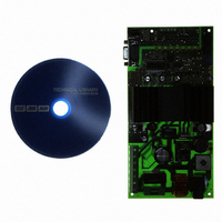
ATAVRMC200 Atmel, ATAVRMC200 Datasheet - Page 12

ATAVRMC200
Manufacturer Part Number
ATAVRMC200
Description
KIT EVAL FOR AT90PWM3 ASYNC
Manufacturer
Atmel
Series
AVR®r
Specifications of ATAVRMC200
Main Purpose
Power Management, Motor Control
Embedded
Yes, MCU, 8-Bit
Utilized Ic / Part
AT90PWM3
Primary Attributes
AC Asynchronous Motors & Brushless DC (BLDC) Motors
Secondary Attributes
Short-Circuit & Thermal Protection
Processor To Be Evaluated
AT90PWM3
Interface Type
RS-232, ISP
Applications
Motor Control
Lead Free Status / RoHS Status
Lead free / RoHS Compliant
3.6
3.7
3.7.1
ATAVRMC200 Hardware User Guide
Opto isolated Area
UART Opto Isolated
Hardware Overcurrent Detection
The current into each phase of the motor is controlled by hardware using analog to digi-
tal converter, it allows to turn off all Mosfets when overcurrent occurs. A reference
voltage is generated throught digital to analog converter of the AT90PWM3, This signal
is used as current reference, and adapts the reference for events such as inrush current
when the motor starts rotating.
The ATAVRMC200 board has an opto isolated area (in grey below) allowing to connect
the board to external link when the board is powered by 110/220V AC.
The opto isolated uart (connector J7) is connected to Rxd and Txd pin of AT90PWM3, it
allows full duplex communication. Users may use a nine wire to wire cable to connect
ATAVRMC200 to PC or terminal. The maximum baud rates is 38400 bauds.
Uart is self powered by PC using RTS and CTS pins, for that reason, uart must be used
with no flux control.
Figure 3-5 . Position of opto isolated area and uart connector
Uart connector
Otpo isolated area in grey
7638A–AVR–05/06
9


