EVL6563S-250W STMicroelectronics, EVL6563S-250W Datasheet - Page 14
EVL6563S-250W
Manufacturer Part Number
EVL6563S-250W
Description
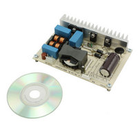
EVAL BOARD FOR L6563(250W)
Manufacturer
STMicroelectronics
Type
Power Factor Correctionr
Specifications of EVL6563S-250W
Main Purpose
Power Management, Power Factor Correction
Embedded
No
Utilized Ic / Part
L6563
Primary Attributes
250W Power Factor Correction and Preregulator Combination
Secondary Attributes
Transition Mode & Active Tracking Boost Function.
Board Size
88 mm x 116 mm
Maximum Operating Temperature
+ 50 C
Operating Supply Voltage
90 V to 265 V
Product
Power Management Modules
Dimensions
88 mm x 116 mm
Lead Free Status / RoHS Status
Lead free / RoHS Compliant
For Use With/related Products
L6563S
Other names
497-10489
Available stocks
Company
Part Number
Manufacturer
Quantity
Price


Test results and significant waveforms
14/32
Figure 16. EVL6563S-250W TM PFC: MOSFET
CH1: Q1 gate voltage, CH2: Q2 gate voltage,
CH3: Q1 drain current
CH4: Q2 drain current
Figure 18. EVL6563S-250W TM PFC: L6563S
CH1: GD - pin #13, CH2: ZCD - pin #11, CH3: CS - pin #4
CH4: MULT - pin #3
filtering needs. In fact, a large capacitance introduces a conduction dead-angle of the AC
input current in itself, therefore reducing the effectiveness of the optimizer circuit.
In
transition mode control; once the inductor has transferred all the energy stored, a falling
edge on the ZCD pin (#11) is detected and it triggers a new on-time by setting the gate drive
high. Once the current signal on the CS pin (#4) has reached the level programmed by the
internal multiplier circuitry, according to the input mains instantaneous voltage and the error
amplifier output level, the gate drive is set low and MOSFET conduction is stopped. During
the following off-time the energy stored in the inductor is transferred into the output capacitor
and to the load. At the end of the current conduction a new demagnetization is detected by
the ZCD which provides for a new on-time of the MOSFET.
In
current at 100 Vac - 50 Hz - full load
control pins-1 at 115 Vac - 60 Hz -
full load
Figure 18
Figure 19
the detail of the waveforms at switching frequency shows the operation of the
the waveforms of the MULT, V
Doc ID 16849 Rev 2
Figure 17. EVL6563S-250W TM PFC: MOSFET
CH1: Q1 gate voltage, CH2: Q2 gate voltage
CH3: Q1 drain current
CH4: Q2 drain current
Figure 19. EVL6563S-250W TM PFC: L6563S
CH1: INV - pin #1, CH2: MULT - pin #3, CH3: COMP - pin #2
CH4: V
FF
, INV, and COMP pins are shown.
FF
- pin #5
current at 100 Vac - 50 Hz - full load
control pins-2 at 115 Vac - 60 Hz -
full load
AN3119
Related parts for EVL6563S-250W
Image
Part Number
Description
Manufacturer
Datasheet
Request
R

Part Number:
Description:
EVAL BOARD FOR L6563(100W)
Manufacturer:
STMicroelectronics
Datasheet:

Part Number:
Description:
EVAL BOARD FOR L6563(400W)
Manufacturer:
STMicroelectronics
Datasheet:

Part Number:
Description:
Power Management Modules & Development Tools Tranisition Mode PFC L6563S EVL Board
Manufacturer:
STMicroelectronics
Datasheet:

Part Number:
Description:
EVAL BOARD L6563 (200W)
Manufacturer:
STMicroelectronics
Datasheet:
Part Number:
Description:
STMicroelectronics [RIPPLE-CARRY BINARY COUNTER/DIVIDERS]
Manufacturer:
STMicroelectronics
Datasheet:
Part Number:
Description:
STMicroelectronics [LIQUID-CRYSTAL DISPLAY DRIVERS]
Manufacturer:
STMicroelectronics
Datasheet:

Part Number:
Description:
BOARD EVAL FOR MEMS SENSORS
Manufacturer:
STMicroelectronics
Datasheet:
Part Number:
Description:
NPN TRANSISTOR POWER MODULE
Manufacturer:
STMicroelectronics
Datasheet:
Part Number:
Description:
TURBOSWITCH ULTRA-FAST HIGH VOLTAGE DIODE
Manufacturer:
STMicroelectronics
Datasheet:
Part Number:
Description:
Manufacturer:
STMicroelectronics
Datasheet:
Part Number:
Description:
DIODE / SCR MODULE
Manufacturer:
STMicroelectronics
Datasheet:
Part Number:
Description:
DIODE / SCR MODULE
Manufacturer:
STMicroelectronics
Datasheet: