STEVAL-IPT002V1 STMicroelectronics, STEVAL-IPT002V1 Datasheet - Page 19
STEVAL-IPT002V1
Manufacturer Part Number
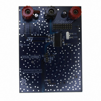
STEVAL-IPT002V1
Description
BOARD EVAL SMART CARD
Manufacturer
STMicroelectronics
Specifications of STEVAL-IPT002V1
Main Purpose
Memory, Smart Card
Embedded
No
Utilized Ic / Part
ST8024
Primary Attributes
New Digital Systems (NDS) Compatible
Secondary Attributes
Short-Circuit & Thermal Protection
Product
Power Management Modules
Silicon Manufacturer
ST Micro
Silicon Core Number
ST8024
Kit Application Type
Interface
Application Sub Type
Smart Card Interface
Kit Contents
Board CD Docs
Lead Free Status / RoHS Status
Lead free / RoHS Compliant
Other names
497-8939
Available stocks
Company
Part Number
Manufacturer
Quantity
Price
Company:

Part Number:
STEVAL-IPT002V1
Manufacturer:
STMicroelectronics
Quantity:
1


5.5
5.6
Inactive mode
After a power-on reset, the circuit enters the inactive mode. A minimum number of circuits
are active while waiting for the microcontroller to start a session:
Activation sequence
After power-on and after the internal pulse width delay, the system microcontroller can
check the presence of a card using the signals OFF and CMDVCC as shown in
If the card is in the reader (this is the case if PRES or PRES is active), the system
microcontroller can start a card session by pulling CMDVCC LOW. The following sequence
then occurs (see
If the applied clock is not needed, then CMDVCC may be set LOW with RSTIN LOW. In this
case, CLK will start at t
may be set HIGH in order to obtain an Answer To Request (ATR) from the card.
Activation should not be performed with RSTIN held permanently HIGH
Table 22.
– All card contacts are inactive (approximately 200 Ω to GND)
– Pins I/OUC, AUX1UC and AUX2UC are in the high-impedance state (11 kΩ pull-up
– Voltage generators are stopped
– XTAL oscillator is running
– Voltage supervisor is active
– The internal oscillator is running at its low frequency.
1. CMDVCC is pulled LOW and the internal oscillator changes to its high frequency (t
2. The voltage doubler is started (between t
3. V
64 times the period of the internal oscillator (approximately 25 µs).
4. I/O, AUX1 and AUX2 are enabled (t
moment).
5. CLK is applied to the C3 contact of the card reader (t
6. RST is enabled (t
The clock may be applied to the card using the following sequence (see
1. Set RSTIN HIGH.
2. Set CMDVCC LOW.
3. Reset RSTIN LOW between t
4. RST remains LOW until t
5. After t
pulses before toggling RST.
resistor to V
CC
rises from 0 to 5 V (or 3 V) with a controlled slope (t
Card presence indicator
OFF
5
, RSTIN has no further affect on CLK; this allows a precise count of CLK
H
L
Figure
DD
)
3
6):
(minimum 200 ns after the transition on I/O), and after t
5
= t
1
+ 7T).
5
, when RST is enabled to be the copy of RSTIN.
3
and t
CMDVCC
3
5
= t
; CLK will start at this moment.
H
H
1
0
+ 4T) (these were pulled LOW until this
and t
1
).
4
).
2
= t
1
Card not present
+ 1.5 x T) where T is
Card present
Indication
Figure
Table
5
, RSTIN
5):
22.
19/31
0
).
Related parts for STEVAL-IPT002V1
Image
Part Number
Description
Manufacturer
Datasheet
Request
R

Part Number:
Description:
BOARD DEMO TFT DISPLAY STR91
Manufacturer:
STMicroelectronics
Datasheet:

Part Number:
Description:
BOARD EVAL FOR MEMS SENSORS
Manufacturer:
STMicroelectronics
Datasheet:

Part Number:
Description:
KIT DEV STARTER ST10F276Z5
Manufacturer:
STMicroelectronics
Datasheet:

Part Number:
Description:
BOARD EVAL HDMI $ VIDEO SWITCH
Manufacturer:
STMicroelectronics
Datasheet:

Part Number:
Description:
BOARD DEMO ACCELEROMETER DIL24
Manufacturer:
STMicroelectronics
Datasheet:

Part Number:
Description:
BOARD STLM75/STDS75/ST72F651
Manufacturer:
STMicroelectronics
Datasheet:

Part Number:
Description:
EVAL BOARD 3AXIS MEMS ACCELLRMTR
Manufacturer:
STMicroelectronics
Datasheet:

Part Number:
Description:
BOARD EVAL 8BIT MICRO + TDE1708
Manufacturer:
STMicroelectronics
Datasheet:

Part Number:
Description:
EVAL BOARD A/D TS4657
Manufacturer:
STMicroelectronics
Datasheet:

Part Number:
Description:
BOARD ADAPTER 20DIP LIS3LV02DL
Manufacturer:
STMicroelectronics
Datasheet:
Part Number:
Description:
STMicroelectronics [RIPPLE-CARRY BINARY COUNTER/DIVIDERS]
Manufacturer:
STMicroelectronics
Datasheet:
Part Number:
Description:
STMicroelectronics [LIQUID-CRYSTAL DISPLAY DRIVERS]
Manufacturer:
STMicroelectronics
Datasheet:
Part Number:
Description:
BOARD EVAL FOR MEMS SENSORS
Manufacturer:
STMicroelectronics
Datasheet: