STEVAL-IPE009V1 STMicroelectronics, STEVAL-IPE009V1 Datasheet - Page 26
STEVAL-IPE009V1
Manufacturer Part Number
STEVAL-IPE009V1
Description
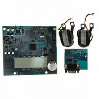
BOARD EVAL ST72321BR9/STPM14
Manufacturer
STMicroelectronics
Type
Other Power Managementr
Specifications of STEVAL-IPE009V1
Main Purpose
Power Management, Energy/Power Meter
Embedded
Yes, MCU, 8-Bit
Utilized Ic / Part
STPM14, ST72F321BR9T6
Primary Attributes
1-Ph 220 VAC, LCD Displays: No-Load, Reverse, Fraud, or Case Tampering
Secondary Attributes
Up to 4 Tariff Rates, Data Accumulated for Meter Life, Time Stamp for: Tamper, Fraud, Power Failure
Input Voltage
220 V
Product
Power Management Modules
Silicon Manufacturer
ST Micro
Silicon Core Number
ST72321BR9 And STPM14
Features
Continuously Detects, Displays No-Load Condition, Reverse Direction, Fraud And Case Tamper Condition
Lead Free Status / RoHS Status
Lead free / RoHS Compliant
For Use With/related Products
STPM14, ST72321BR9
Other names
497-8434
STEVAL-IPE009V1
STEVAL-IPE009V1


Theory of operation
Figure 19. Positive energy stepper driving signals
Figure 20. Negative energy stepper driving signals
7.15
26/46
When a no-load condition is detected MOP and MON are held low.
Configuring the STPM1x
All the configuration bits that control the operation of the device can be written temporarily or
permanently. For temporary writing, the configuration bits value are written in the shadow
registers which are simple latches that hold the configuration data. For permanent writing,
the configuration bits are stored in the OTP (one time programmable) cells that keep the
information for an undefined period of time even if the STPM1X is without supply, but, once
written, they cannot be changed. The temporary writing is useful mainly during testing of the
device or during the calibration phase. All the configuration parameters can be changed an
infinite number of times in order to test the device operation.
The shadow registers are cleared whenever a reset condition occurs.
The configuration bits are different for STPM11/12 and for STPM13/14 due to the presence
of the Tamper module. Each of them consists of paired elements, one is latch (the OTP
shadow), and one is the OTP antifuse element. When the STPM1X is released in the
market, all anti-fuses represent logic low state but they can be written by the user in order to
configure the STPM1X. This means that STPM1X can retain these bits of information even if
it has been unsupplied for an undefined time. That's why the CFG signals are used to keep
certain configuration and calibration values of the device.
Hi
Lo
Hi
Lo
Hi
Lo
Hi
Lo
Doc ID 13167 Rev 7
MON
MON
MOP
MOP
STPM11, STPM12, STPM13, STPM14
Related parts for STEVAL-IPE009V1
Image
Part Number
Description
Manufacturer
Datasheet
Request
R

Part Number:
Description:
BOARD DEMO TFT DISPLAY STR91
Manufacturer:
STMicroelectronics
Datasheet:

Part Number:
Description:
BOARD EVAL FOR MEMS SENSORS
Manufacturer:
STMicroelectronics
Datasheet:

Part Number:
Description:
KIT DEV STARTER ST10F276Z5
Manufacturer:
STMicroelectronics
Datasheet:

Part Number:
Description:
BOARD EVAL HDMI $ VIDEO SWITCH
Manufacturer:
STMicroelectronics
Datasheet:

Part Number:
Description:
BOARD DEMO ACCELEROMETER DIL24
Manufacturer:
STMicroelectronics
Datasheet:

Part Number:
Description:
BOARD STLM75/STDS75/ST72F651
Manufacturer:
STMicroelectronics
Datasheet:

Part Number:
Description:
EVAL BOARD 3AXIS MEMS ACCELLRMTR
Manufacturer:
STMicroelectronics
Datasheet:

Part Number:
Description:
BOARD EVAL 8BIT MICRO + TDE1708
Manufacturer:
STMicroelectronics
Datasheet:

Part Number:
Description:
EVAL BOARD A/D TS4657
Manufacturer:
STMicroelectronics
Datasheet:

Part Number:
Description:
BOARD ADAPTER 20DIP LIS3LV02DL
Manufacturer:
STMicroelectronics
Datasheet:
Part Number:
Description:
STMicroelectronics [RIPPLE-CARRY BINARY COUNTER/DIVIDERS]
Manufacturer:
STMicroelectronics
Datasheet:
Part Number:
Description:
STMicroelectronics [LIQUID-CRYSTAL DISPLAY DRIVERS]
Manufacturer:
STMicroelectronics
Datasheet:
Part Number:
Description:
BOARD EVAL FOR MEMS SENSORS
Manufacturer:
STMicroelectronics
Datasheet: