EVB-USB2524 SMSC, EVB-USB2524 Datasheet - Page 40
EVB-USB2524
Manufacturer Part Number
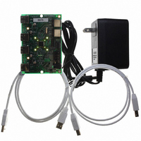
EVB-USB2524
Description
BOARD EVAL USB2524 SHARE/SWITCH
Manufacturer
SMSC
Series
MultiSwitch™r
Specifications of EVB-USB2524
Main Purpose
Interface, USB 2.0 Hub
Embedded
No
Utilized Ic / Part
USB2524
Primary Attributes
Quad Port Hub, High Speed (480Mbps), SMBus
Secondary Attributes
Overcurrent Protection, Port Power Switching, Multi-TT Enabled
Interface Type
USB
Operating Supply Voltage
5 V
Product
Interface Modules
Lead Free Status / RoHS Status
Lead free / RoHS Compliant
For Use With/related Products
USB2524
Other names
638-1044
Available stocks
Company
Part Number
Manufacturer
Quantity
Price
Company:

Part Number:
EVB-USB2524
Manufacturer:
SMSC
Quantity:
135


Revision 1.91 (08-22-07)
7.2
7.2.1
7.2.1.1
7.2.1.2
7.2.1.3
7.2.2
The SMSC Hub can be configured via a 2-wire (I
or EEPROM Interface Behavior"
EEPROM).
The Internal state-machine will, (when configured for EEPROM support) read the external EEPROM
for configuration data. The hub will then “attach” to the upstream USB port.
Note: The Hub does not have the capability to write, or “Program”, an external EEPROM. The Hub
Please see Internal Register Set (Common to EEPROM and SMBus) for a list of data fields available.
I
The I
Philips Semiconductor Standard I
EEPROM interface is designed to attach to a single “dedicated” I
Standard-mode I
electrical compatibility.
Note: Extensions to the I
The Hub acts as the master and generates the serial clock SCL, controls the bus access (determines
which device acts as the transmitter and which device acts as the receiver), and generates the START
and STOP conditions.
Implementation Characteristics
The Hub will only access an EEPROM using the Sequential Read Protocol.
Pull-Up Resistor
The Circuit board designer is required to place external pull-up resistors (10KΩ recommended) on the
SDA/SMBDATA & SCL/SMBCLK/CFG_SELO lines (per SMBus 1.0 Specification, and EEPROM
manufacturer guidelines) to Vcc in order to assure proper operation.
I
Slave address is 1010000.
Note: 10-bit addressing is NOT supported.
In-Circuit EEPROM Programming
The EEPROM can be programmed via ATE by pulling RESET_N low (which tri-states the Hub’s
EEPROM interface and allows an external source to program the EEPROM).
EEPROM Interface
2
2
C EEPROM Slave Address
C Master
2
C EEPROM interface implements a subset of the I
only has the capability to read external EEPROMs. The external eeprom will be read (even if
it is blank or non-populated), and the hub will be “configured” with the values that are read.
2
C Specification (100kbit/s transfer rate and 7-bit addressing) for protocol and
2
C Specification are not supported.
2
C-Bus Specification for details on I
DATASHEET
for specific details on how to enable configuration via an I
40
2
C) EEPROM (256x8). (please see
2
C Master Specification (Please refer to the
2
C EEPROM, and it conforms to the
2
C bus protocols). The Hub’s I
USB MultiSwitch
Table 4.2, "SMBus
SMSC USB2524
Datasheet
TM
Hub
2
2
C
C
Related parts for EVB-USB2524
Image
Part Number
Description
Manufacturer
Datasheet
Request
R

Part Number:
Description:
BOARD EVAL FOR USB2514 48-QFN
Manufacturer:
SMSC
Datasheet:

Part Number:
Description:
Networking Modules & Development Tools LAN7500 USB 2.0 BRD 10/100/1000 GigB
Manufacturer:
SMSC
Datasheet:

Part Number:
Description:
BOARD EVAL FOR USB2514/USB2514I
Manufacturer:
SMSC
Datasheet:

Part Number:
Description:
BOARD EVAL FOR USB2512/USB2512I
Manufacturer:
SMSC
Datasheet:

Part Number:
Description:
BOARD EVAL FOR USB2513/USB2513I
Manufacturer:
SMSC
Datasheet:

Part Number:
Description:
BOARD EVALUATION FOR EMC1043
Manufacturer:
SMSC
Datasheet:
Part Number:
Description:
EVALUATION BOARD FOR USB3311C
Manufacturer:
SMSC
Datasheet:
Part Number:
Description:
EVALUATION BOARD FOR USB3317C
Manufacturer:
SMSC
Datasheet:

Part Number:
Description:
EVALUATION BOARD USB2241-AEZG
Manufacturer:
SMSC
Datasheet:

Part Number:
Description:
BOARD EVALUATION FOR USB2502
Manufacturer:
SMSC
Datasheet:
Part Number:
Description:
BOARD EVALUATION FOR USB2504
Manufacturer:
SMSC
Datasheet:

Part Number:
Description:
EVALUATION BOARD LAN9500-ABZJ
Manufacturer:
SMSC
Datasheet:
Part Number:
Description:
Ethernet Modules & Development Tools LAN9500 Design Kit Low-Cost USB Dongle
Manufacturer:
SMSC
Datasheet:
Part Number:
Description:
Interface Modules & Development Tools Eval BRD-USB2602
Manufacturer:
SMSC
Datasheet: