ADNK-3083 Avago Technologies US Inc., ADNK-3083 Datasheet - Page 4
ADNK-3083
Manufacturer Part Number
ADNK-3083
Description
KIT REFERENCE DESIGN ADNS-3080
Manufacturer
Avago Technologies US Inc.
Specifications of ADNK-3083
Main Purpose
Reference Design, Optical Mouse
Utilized Ic / Part
ADNS-3080, CY7C63743-PXC, CY7C63743A
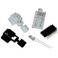
Kit Contents
ADNS-3080 Sensor, UP, Hardware And Documentation
Peak Reflow Compatible (260 C)
Yes
Tool / Board Applications
Optical Mouse Sensors
Description/function
Optical Mouse Sensor Kit
Interface Type
USB
Product
Display Modules
Touch Panel
No Touch Panel
Development Tool Type
Hardware / Software - Dev Kit (Dev Tool)
Rohs Compliant
Yes
For Use With
ADNS-3080
Lead Free Status / RoHS Status
Lead free / RoHS Compliant
Secondary Attributes
-
Embedded
-
Primary Attributes
-
Lead Free Status / Rohs Status
Details
For Use With/related Products
CY7C63743-PXC, CY7C63743A-PC
Lead Free Status / RoHS Status
Lead free / RoHS Compliant, Lead free / RoHS Compliant


USB and PS/2 Connection
The CY7C63743-PXC has a configuration register that
switches control from the SIE to manual control on the
D+ and D- pins. This allows the firmware to dynamically
configure itself to operate as a USB or PS/2 mouse, allow-
ing signal lines to be shared without using extra GPIO pins
for PS/2 operation. The firmware for this reference design
will automatically detect the host topology (USB or PS/2)
at plug-in, and will configure itself for operation on that
bus. If a USB host connection is detected, the firmware
will enable the VREG pin, such that the 1.3k ohm resis-
tor connected to the D- line, can be pulled up to 3.3V.
Through this action, the host is able to recognize there is
a lowspeed USB peripheral attached. These connections
are shown in Figure 3 below.
ADNK-3083 Designer’s Kit— Optical Mouse
The ADNK-3083 optical mouse unit allows users to
evaluate the performance of the Avago’s Optical Tracking
Engine (sensor, lens, LED assembly clip, LED) over both
a USB or PS/2 connection, using a Cypress enCoRe USB
Controller. This kit also enables users to understand the
recommended mechanical assembly. (See Appendices
C, D, and E).
System Requirements
PCs using Windows® 95/ Windows® 98/ Windows® NT/
Windows® 2000 with PS/2 port and standard 3-button
USB mouse driver loaded.
Figure 3. USB and PS/2 peripheral connectors.
Figure 4. Exploded view drawing of optical tracking engine with ADNS-3080 optical
mouse sensor.
Figure 5. Distance from lens reference plane to surface.
(0.094 in)
2.40 mm
Functionality
3-button, scroll wheel mouse.
Operating (For PS/2 Mode)
Step 1: Turn off the PC.
Step 2: Plug the mouse unit’s PS/2 connector into the
PC’s PS/2 port.
Step 3: Turn on the PC. All of the mouse buttons and scroll
wheel will function exactly like a standard PS/2 mouse.
Operating (For USB Mode)
Hot pluggable with USB port. The PC does not need to
be powered off when plugging or unplugging the evalu-
ation mouse.
To Disassemble the ADNK-3083 Unit
The ADNK-3083 comprises of the plastic mouse casing,
printed circuit board (PCB), lens, buttons, and USB cable.
(See Figure 4.) Unscrewing the one screw located at the
base of the unit can open the ADNK-3083 unit. Lifting
and pulling the PCB out of the base plate can further
disassemble the mouse unit.
While reassembling the components, please make sure
that the Z height (Distance from lens reference plane to
surface) is valid. Refer to Figure 5.
Sensor
Object Surface
Lens
Related parts for ADNK-3083
Image
Part Number
Description
Manufacturer
Datasheet
Request
R

Part Number:
Description:
ADNK-3000 Sample Kit
Manufacturer:
Avago Technologies US Inc.
Datasheet:

Part Number:
Description:
KIT REFERENCE DESIGN ADNK-3060
Manufacturer:
Avago Technologies US Inc.
Datasheet:

Part Number:
Description:
KIT REFERENCE DESIGN ADNK-5030
Manufacturer:
Avago Technologies US Inc.
Datasheet:
Part Number:
Description:
KIT DES BLUETOOTH OPT ADNK-3043
Manufacturer:
Avago Technologies US Inc.
Datasheet:
Part Number:
Description:
KIT SAMPLE FOR ADNS-5030
Manufacturer:
Avago Technologies US Inc.
Datasheet:
Part Number:
Description:
KIT SAMPLE OPT MOUSE ADNS-3550
Manufacturer:
Avago Technologies US Inc.
Datasheet:
Part Number:
Description:
KIT SAMPLE OPT MOUSE ADNS-5000
Manufacturer:
Avago Technologies US Inc.
Datasheet:

Part Number:
Description:
KIT SAMPLE OPTICAL MOUSE A5050
Manufacturer:
Avago Technologies US Inc.
Datasheet:
Part Number:
Description:
KIT SAMPLE OPT MOUSE ADNS-5060
Manufacturer:
Avago Technologies US Inc.
Datasheet:

Part Number:
Description:
OPTOCOUPLER GATE DRV 2A 16-SOIC
Manufacturer:
Avago Technologies US Inc.
Datasheet:
Part Number:
Description:
OPTOCOUPLER 2CH 2.5A 16-SOIC
Manufacturer:
Avago Technologies US Inc.
Datasheet:

Part Number:
Description:
OPTOCOUPLER GATE DRV 0.4A 16SOIC
Manufacturer:
Avago Technologies US Inc.
Datasheet:

Part Number:
Description:
OPTOCOUPLER 2.0A 250KHZ 8-DIP
Manufacturer:
Avago Technologies US Inc.
Datasheet:

Part Number:
Description:
OPTOCOUPLER 2.0A 250KHZ GW 8-SMD
Manufacturer:
Avago Technologies US Inc.
Datasheet: