EVAL-ADCMP581BCPZ Analog Devices Inc, EVAL-ADCMP581BCPZ Datasheet
EVAL-ADCMP581BCPZ
Specifications of EVAL-ADCMP581BCPZ


Related parts for EVAL-ADCMP581BCPZ


EVAL-ADCMP581BCPZ Summary of contents
Page 1
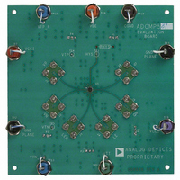
... Evaluation Board for ADCMP572/ ADCMP573/ADCMP580/ADCMP581/ADCMP582 EVAL-ADCMP572/573/580/581/582 EVALUATION BOARD DESCRIPTION Figure photograph of the top of the evaluation board fabricated using a high quality dielectric material between the ground plane and signal layers in order to maintain high signal integrity. All input and output signals are brought on to the board with 2 connectors, and transmission line paths are kept as close to 50 Ω ...
Page 2
... TABLE OF CONTENTS General Description ......................................................................... 1 Evaluation Board Description......................................................... 1 Package List ....................................................................................... 1 Evaluation Board .............................................................................. 1 Revision History ............................................................................... 2 Using the Evaluation Board............................................................. 3 Measurements ............................................................................... 3 Setting Up the Evaluation Board .................................................... 4 Connect Power.............................................................................. 4 Connect Inputs ............................................................................. 8 REVISION HISTORY 2/06—Revision 0: Initial Version Setup Input Signals........................................................................8 Connect Output Signals ...............................................................8 Jumper Setup......................................................................................9 Test Setup......................................................................................... 10 Additional Support ...
Page 3
... USING THE EVALUATION BOARD MEASUREMENTS The same PCB is used to evaluate both ADCMP57x and ADCMP58x families. The Setting Up the Evaluation Board section describes the measurements that can be performed with this evaluation board. EVAL-ADCMP572/573/580/581/582 Table 1. Basic Equipment Description Example Equipment Power Supply with ...
Page 4
... EVAL-ADCMP572/573/580/581/582 SETTING UP THE EVALUATION BOARD CONNECT POWER Several power supply levels must be provided to the board for CGND (the comparator’s GND pin), and CCI CCO EE TT GND via the banana jacks. Make a direct connection from the DUT output pins to the oscilloscope because any transmission line discontinuity degrades performance ...
Page 5
... GND is always system ground NOTES 1. GND HERE BECOMES BOARD CGND. 1 ADCMP582(PECL) 3.7 V 2.0 V −6.3 V −6 −1 CCI CCO ADCMP582 RSPECL – INPUT 14 HYS LE INPUT V GND EE Figure 4. ADCMP582 Power Supply Connections Rev Page EVAL-ADCMP572/573/580/581/582 2 ADCMP582(PECL) 4.5 V 2.0 V −5.5 V −5 −0 OUTPUT Q OUTPUT ...
Page 6
... EVAL-ADCMP572/573/580/581/582 Table 4. ADCMP572 Power Supply and Input Translation Pin Case 1 V 0.0 V CCI V 0.0 V CCO CGND − −3.5V < LE/LE 0.0 V/−0.4 V AGND 0.0 V (This is not a pin in the part 3.3 V. CCI CCO 5 3.3 V. CCI CCO 5.2 V. CCI CCO V V NOTES 1. GND HERE BECOMES BOARD CGND. ...
Page 7
... V −1 0 < −0.1 V −1.5 V < 1.2 V/0 CCI CCO ADCMP573 CML – INPUT 14 HYS LE INPUT GND GND Figure 6. ADCMP573 Power Supply Connections Rev Page EVAL-ADCMP572/573/580/581/582 3 Case 3 2.0 V 2.0 V −3 0 < +1.9 V −3.4 V < 1.2 V/0 OUTPUT Q OUTPUT < 0.0 V ...
Page 8
... EVAL-ADCMP572/573/580/581/582 CONNECT INPUTS Connect the differential output of the generator to the differential comparator input pins of the device, V Connect the differential data output of the generator to the differential latch input of the device, LE and LE . SETUP INPUT SIGNALS Input and latch levels must be shifted consistently with the power supplies (see Table 4 through Table 7) ...
Page 9
... P5 Short 1, 2 Short 2, 3 EVAL-ADCMP572/573/580/581/582 If the evaluation board used for a different comparator type than was mounted on the board originally, pull all the jumpers to prevent errors. Once the new part type is installed, the jumpers can be reinstalled. Table 8 gives the correct jumper settings and resulting banana jack connections for each of the comparator products ...
Page 10
... EVAL-ADCMP572/573/580/581/582 TEST SETUP Figure 2 shows Analog Devices’ test configuration setup that was used for much of the initial engineering evaluation provided here as a guideline and to assist in replicating our setup. AGILENT E3631A TRIPLE POWER SUPPLY KEITHLEY 2400 SOURCE METER ADDITIONAL SUPPORT For further support regarding the ADCMP572/ADCMP573 and ADCMP580/ADCMP581/ADCMP582 comparators and/or evaluation boards, refer to www ...
Page 11
... SCHEMATICS EVAL-ADCMP572/573/580/581/582 C21 .1UF C16 .1UF C17 .1UF C20 1 .1UF C3 .1UF C8 VCCI VCCI 5 16 VCC_1 VCC_2 .1UF LEB GND VTT C2 .1UF C25 C1 .1UF .1UF C22 C30 .1UF .1UF C23 C26 .1UF .1UF C24 C27 .1UF .1UF C29 .1UF Figure 8. Schematic, Main Rev ...
Page 12
... EVAL-ADCMP572/573/580/581/582 VCCI VEE TP13 BLU APLANE TP7 RED TP2 BLK APLANE APLANE TP6 ORG TP3 BLK APLANE APLANE TP12 BLU VTN_F APLANE TP10 BRN CGND APLANE Figure 9. Schematic, Bypass Capacitors Rev Page TP9 VIO VCC0 APLANE TP11 GRN VTT_PLANE APLANE VTP_F ...
Page 13
... PC BOARD EVAL-ADCMP572/573/580/581/582 Figure 10. Bottom Signal Layer Figure 11. GND Plane Rev Page ...
Page 14
... EVAL-ADCMP572/573/580/581/582 Figure 12. V Plane CC Figure 13. GND Plane Rev Page ...
Page 15
... EVAL-ADCMP572/573/580/581/582 Figure 14. Miscellaneous DC Plane Figure 15. GND Plane Rev Page ...
Page 16
... EVAL-ADCMP572/573/580/581/582 Figure 16. Upper Plane Figure 17. Top Rev Page ...
Page 17
... EVAL-ADCMP572/573/580/581/582 Figure 18. Solder Mask Figure 19. Solder Mask Rev Page ...
Page 18
... EVAL-ADCMP572/573/580/581/582 SILKSCREENS Figure 20. Silkscreen Bottom Figure 21. Silkscreen Top Rev Page ...
Page 19
... COMPONENTS EVAL-ADCMP572/573/580/581/582 Figure 22 Bottom Components Figure 23. Top Components Rev Page ...
Page 20
... EVAL-ADCMP572/573/580/581/582 ORDERING INFORMATION ORDERING GUIDE Model Package Description EVAL-ADCMP572BCP Evaluation Board EVAL-ADCMP573BCP Evaluation Board EVAL-ADCMP580BCP Evaluation Board EVAL-ADCMP581BCP Evaluation Board EVAL-ADCMP582BCP Evaluation Board ESD CAUTION ESD (electrostatic discharge) sensitive device. Electrostatic charges as high as 4000 V readily accumulate on the human body and test equipment and can discharge without detection. Although this product features proprietary ESD protection circuitry, permanent damage may occur on devices subjected to high energy electrostatic discharges ...