CDB4271 Cirrus Logic Inc, CDB4271 Datasheet
CDB4271
Specifications of CDB4271


Related parts for CDB4271


CDB4271 Summary of contents
Page 1
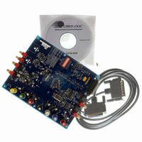
... Analog Outputs Cirrus Logic, Inc. www.cirrus.com Description The CDB4271 demonstration board is an excellent means for evaluating the CS4271 stereo CODEC. Eval- uation requires an analog/digital signal source and analyzer, and power supplies. Optionally, a Windows PC compatible computer may be used to evaluate the CS4271 in control port mode. ...
Page 2
... I2C is a registered trademark of Philips Semiconductor. Purchase of I2C Components of Cirrus Logic, Inc., or one of its sublicensed Associated Companies conveys a license under the Philips I2C Patent Rights to use those components in a standard I2C system. Microsoft Windows is a registered trademark of Microsoft Corporation. 2 CDB4271 ...
Page 3
... Figure 13. PCM Header, Schematic Sheet 8 ................................................................................ 23 Figure 14. Control Port, Schematic Sheet 9.................................................................................. 24 Figure 15. Power, Schematic Sheet 10......................................................................................... 25 Figure 16 . Component Placement and Reference Designators.................................................. 26 Figure 17 . Top Layer................................................................................................................... 27 Figure 18 . Bottom Layer.............................................................................................................. 28 Figure 19 . Complete Analog Input Buffer Schematic .................................................................. 29 LIST OF TABLES Table 1. System Connections ......................................................................................................... 9 Table 2. Jumper/Switch Settings................................................................................................... 10 CDB4271 3 ...
Page 4
... The operation of the CS8416 receiver (see Figure 10) and a discussion of the digital audio interface are included in the CS8416 data sheet. The CS8416 converts the input S/PDIF data stream into PCM data for the CS4271. The CDB4271 is able to operate the CS8416 in master or slave mode. Digital Interface format se- lection of either Left Justified Right Justified interface formats can be selected via the control port GUI ...
Page 5
... RCA connectors supply the CS4271 analog inputs through unity gain, AC-coupled single- ended circuits Vrms single-ended signal will drive the CS4271 inputs to full scale. The CDB4271 was designed for use with not only the CS4271, but also the CS4272 with a simple change of assembly options. For this reason, the input buffer schematic shown in Figure 8 reflects only the configuration assembled on the CDB4271 ...
Page 6
... DC-block capacitor (C26 for AOUTR). For LPF configuration 2, the values for the DC-block capacitor and output resistor pad ( R10 and R22 for AOUTR) were cho- sen to minimize the rise in distortion performance at low frequency due to the electrolytic's 6 In+ + Out Out- In- + CDB4271 ...
Page 7
... S1 and its associated logic. 1.8 PC Parallel Port Control A graphical user interface is included with the CDB4271 to allow easy manipulation of all reg- isters of the CS4271 and hardware configuration of the CDB4271. Connecting a cable to the DB-25 connector (J31) will enable the PC control port, automatically disabling switch S1 and its associated logic ...
Page 8
... Figure 16 shows the component placement, Figure 17 shows the top layout, and Figure 18 shows the bottom layout. The decoupling capacitors are located as close to the CS4271 as possible. Extensive use of ground plane fill in the evaluation board yields large reductions in radiated noise. 8 CDB4271 2 C control signals. The ...
Page 9
... External data source for CS8406 SDIN 2 I/O for external SPI / I C control port signals (J32) and control signal header in/out selection (J34) RCA phono jacks for analog input signal to CS4271 RCA phono jacks for analog outputs Table 1. System Connections CDB4271 2 C control port signals and sys- 9 ...
Page 10
... Voltage source is +3.3 V regulator ADJ Voltage source is J3, VD binding post *+5V Voltage source is J1, +5V binding post +3.3V Voltage source is +3.3 V regulator ADJ Voltage source is J2, VL binding post *1 Selects standard 2-pole filter 2 Inserts instrumentation-amp and resistor divider. Table 2. Jumper/Switch Settings CDB4271 FUNCTION SELECTED *Default factory settings ...
Page 11
... Run port95nt.exe from the CD. After running the program the system will need to be restarted desired, create a shortcut to CDB427X.exe on your desktop. You should now be able to run CDB427X.exe. Double-click on CDB427X.exe or its shortcut. 5) Select the LPT port you are using to connect to the CDB4271. 6) Shut down the application, reset the board, and then restart the application. CDB4271 11 ...
Page 12
... Apply a S/PDIF input signal to the optical connector (OPT1). The converted signal should appear at the analog output jacks AOUTR and AOUTL. 5) Apply an analog input signal to the analog input jacks AINR and AINL. The converted sig- nal should appear at the S/PDIF TX output jacks (J12 and J18). 12 CDB4271 ...
Page 13
... Main Window The main window of the CDB4271 Graphical User Interface allows the user to view and change the configuration of the CS4271 and on-board configuration logic. The Board Setup box contains all the controls necessary to manage clock and data routing and formats. To apply changes to the board, the “Send Board Setup” button must be pressed after making changes within the Board Setup box ...
Page 14
... MCLK is providing the signal. For example, if the board is set up to re- ceive MCLK from the header, be sure that there is an active MCLK signal applied to the MCLK position on the header (J26). See Figure 4 below. 14 Figure 3. Advanced Window Figure 4. I²C Error Message CDB4271 2 C ...
Page 15
... BLOCK DIAGRAM XTI XTO MCLK LRCK SCLK CDB4271 15 ...
Page 16
... SCHEMATICS AND LAYOUT 16 CDB4271 ...
Page 17
... CDB4271 17 ...
Page 18
... CDB4271 ...
Page 19
... CDB4271 19 ...
Page 20
... CDB4271 ...
Page 21
... CDB4271 21 ...
Page 22
... CDB4271 ...
Page 23
... CDB4271 23 ...
Page 24
... CDB4271 ...
Page 25
... CDB4271 25 ...
Page 26
... CDB4271 ...
Page 27
... CDB4271 27 ...
Page 28
... CDB4271 ...