STEVAL-ISB001V1 STMicroelectronics, STEVAL-ISB001V1 Datasheet
STEVAL-ISB001V1
Specifications of STEVAL-ISB001V1
Available stocks


Related parts for STEVAL-ISB001V1


STEVAL-ISB001V1 Summary of contents
Page 1
STD1LNK60Z-based Cell Phone Battery Charger Design Introduction This application note is a Ringing Choke Converter (RCC)-based, step-by-step cell phone battery charger design procedure. The RCC is essential to the self-oscillating fly-back converter, and operates within the Discontinuous Conduction Mode (DCM) ...
Page 2
Table of Contents 1 Power Transformer Design Calculations . . . . . . . . . . . . . . . . . . . . . . . . . . . 5 1.1 Switching Frequency . ...
Page 3
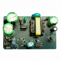
AN2228 - APPLICATION NOTE Figures Figure 1. STD1LNK60Z-based RCC Printed Circuit Board . . . . . . . . . . . . . . . . . . . . . . . . . . . . ...
Page 4
Tables Table 1. Line and Load Regulation . . . . . . . . . . . . . . . . . . . . . . . . . . . . . . . . . ...
Page 5
AN2228 - APPLICATION NOTE 1 Power Transformer Design Calculations The specifications: – 85~265V AC Line frequency: 50~65Hz – – 0.4A O Taking transient load into account, the maximum output current is set ...
Page 6
Power Transformer Design Calculations 1.2 STD1LNK60Z MOSFET Turn Ratio The maximum MOSFET drain voltage must be below its breakdown voltage. The maximum drain voltage is the sum of: input bus voltage, secondary reflected voltage, and voltage spike (caused by ...
Page 7
AN2228 - APPLICATION NOTE 1.3 Primary Current Primary Peak Current is expressed as: I ppk Primary Root Mean Square (RMS) Current is expressed as I prms where Primary peak current ppk V = Voltage output ...
Page 8
Power Transformer Design Calculations 1.5 Magnetic Core Size One of the most common ways to choose a core size is based on Area Product (AP), which is the product of the effective core (magnetic) cross-section area times the window ...
Page 9
AN2228 - APPLICATION NOTE 1.6.2 Wire Diameter The current density (A diameter of primary wire is expressed as where Diameter of primary winding wire Primary RMS current prms A = Current density J 1.6.3 Number ...
Page 10
Power Transformer Design Calculations 1.7 Secondary Winding Using triple insulation wire with a 0.21mm Copper diameter, the number of turns of secondary winding is expressed as where Secondary Winding Turns 168 (total turns for ...
Page 11
AN2228 - APPLICATION NOTE 1.8.2 Wire Diameter With the auxiliary winding turns set outer diameter and a 0.17mm Copper diameter. The Copper diameter of primary wire is expressed as 1.9 Gap Length The gap length setting is ...
Page 12
STD1LNK60Z-based RCC Control Circuit Components 2 STD1LNK60Z-based RCC Control Circuit Components 2.1 MOSFET The STD1LNK60Z (see page 22 ) has built-in, back-to-back Zener diodes specifically designed to enhance not only the Electrostatic Discharge (ESD) protection capability, but also to ...
Page 13
AN2228 - APPLICATION NOTE 2.3 Optocoupler Power Methods There are two methods for powering the optocoupler: fly-back (see Figure 2 forward (see Figure 3 The fly-back method was chosen for the RCC application because it provides more stable power for ...
Page 14
STD1LNK60Z-based RCC Control Circuit Components 2.4 R7 Sense Resistor 2.4.1 Minimum Power Dissipation Sense resistor R7 is used to detect primary peak current limited by its maximum power dissipation, which is set to 0.1% of the maximum ...
Page 15
AN2228 - APPLICATION NOTE Figure 4. Current Sense Circuit R7 2.5 Constant Power Control The pole of capacitor C7 can filter the leading edge current spike and avoid a Q2 switch malfunction. However, it will also lead to delays in ...
Page 16
STD1LNK60Z-based RCC Control Circuit Components Note: R11>> R9 >> R7 this case, only R Note: Constant control accuracy is not as good not used, and applying it is very simple. For the purposes of ...
Page 17
AN2228 - APPLICATION NOTE 2.7 Constant Voltage And Constant Current The Constant Voltage (CV) configuration is comprised of the error amplifier TL431 and C . TL431 provides the reference voltage. R21 and R22 divide the output 22 ...
Page 18
STD1LNK60Z-based RCC Control Circuit Components Figure 5. CV and CC Curve at 110V Note 200V/div; time = 4µs/div) DS Figure 6. CV and CC Curve at 220V 6 5 ...
Page 19
AN2228 - APPLICATION NOTE 3 Test Results Table 1. Line and Load Regulation Supply Voltage 85V AC 110V AC 220V AC 265V AC Line Regulation Note: See Figure 7 and Figure 9 on page 21 Table 2. Efficiency Ratings 85V ...
Page 20
Test Results Figure 7. Drain To Source Voltage Operation Waveform, 85V Note 100V/div; time = 4µs/div DS Figure 8. Drain To Source Voltage Operation Waveform, 110V Note 100V/div; time = 4µs/div DS 20/26 AN2228 - ...
Page 21
AN2228 - APPLICATION NOTE Figure 9. Drain To Source Voltage Operation Waveform, 220V Note 200V/div; time = 4µs/div) DS Figure 10. Drain To Source Voltage Operation Waveform, 265V Note 200V/div; time = 4µs/div Test ...
Page 22
Appendix A: STD1LNK60Z-based RCC Circuit Schematics Appendix A: STD1LNK60Z-based RCC Circuit Schematics Figure 11. RCC Control Circuit Components Schematic (see VDC R2 R3 C13 D5 STD1LNK60Z 3904 C7 Figure 12. STD1LNK60Z-based RCC Schematic (full view) ...
Page 23
AN2228 - APPLICATION NOTE Appendix B: STD1LNK60Z-based RCC Circuit Bill of Materials Table 4. BOM Designator Part Type L1 1mH C1 4.7uF/400V C2 4.7uF/400V C3 222/1KV C4 100u/16V C5 682/60V C6 222/60V C7 472/60V C8 330u/16V C9 47u/16V C10 102/60V ...
Page 24
Appendix B: STD1LNK60Z-based RCC Circuit Bill of Materials Designator Part Type R19 150 R20 2.7 R21 910 R22 1K D1 1N4007 D2 1N4007 D3 1N4007 D4 1N4007 D5 STTH108 D6 1N4148 D7 1N5819 Z1 Jumper Q1 STD1LNK60 IPAK Q2 MMBT3904 ...
Page 25
AN2228 - APPLICATION NOTE 4 Revision History Date Revision 22-August-2005 1.0 First edition 4 Revision History Changes 25/26 ...
Page 26
... No license is granted by implication or otherwise under any patent or patent rights of STMicroelectronics. Specifications mentioned in this publication are subject to change without notice. This publication supersedes and replaces all information previously supplied. STMicroelectronics products are not authorized for use as critical components in life support devices or systems without express written approval of STMicroelectronics ...