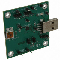
NCP370GEVB ON Semiconductor, NCP370GEVB Datasheet

NCP370GEVB
Specifications of NCP370GEVB
Related parts for NCP370GEVB
NCP370GEVB Summary of contents
Page 1
... Test Procedure for the NCP370GEVB Evaluation Board Test Procedure: 1. Place /REV strap and /DIR strap on left side (“1” logic) (connected to Vbat, through pull up resistor) 2. Let Battery strap opened. 3. Connect a Battery or power supply (4.2V) on Battery test point. (min 2A capability) 1/27/2010 www ...
Page 2
Connect strap on Ilim. 1/27/2010 www.onsemi.com ...
Page 3
Select I limit threshold with pull down resistors connected on pin 7: SW1 SW2 R1= 70K R2= 14K Disable Mode: 6. Connect 10 V capability Vin Supply on IN1 test point. a. Set power supply ...
Page 4
Direct Mode: 7. Switch /DIR from left to right, 1 logic level to 0 logic level 8. Check Vout=5V and Flag LED is still off 9. Set Vin=7V 10. Check Flag LED = on, and Vout is 0V. 11. Switch ...
Page 5
Check Flag LED = off, and Vout = Vin = 7V. Disconnect Vin supply Reverse Mode: 13. Connect Set /DIR=1, /REV=1 Disconnect Vin Power Supply from IN test points. Connect accessory on IN1 or IN2 test points. 14. Set ...


