MCP3424EV Microchip Technology, MCP3424EV Datasheet - Page 10
MCP3424EV
Manufacturer Part Number
MCP3424EV
Description
EVALUATION BOARD FOR MCP3424
Manufacturer
Microchip Technology
Specifications of MCP3424EV
Number Of Adc's
1
Number Of Bits
18
Sampling Rate (per Second)
3.75 ~ 240
Data Interface
I²C
Inputs Per Adc
4 Differential
Input Range
±2.048 V
Power (typ) @ Conditions
135µA @ 240sps
Voltage Supply Source
Single Supply
Operating Temperature
-55°C ~ 125°C
Utilized Ic / Part
MCP3424
Processor To Be Evaluated
MCP3424
Lead Free Status / RoHS Status
Lead free / RoHS Compliant
Lead Free Status / RoHS Status
Lead free / RoHS Compliant, Lead free / RoHS Compliant
Available stocks
Company
Part Number
Manufacturer
Quantity
Price
Company:

Part Number:
MCP3424EV
Manufacturer:
Microchip Technology
Quantity:
135


MCP3424 Evaluation Board User’s Guide
1.3
DS51737A-page 6
GETTING STARTED WITH PICKIT SERIAL ANALYZER
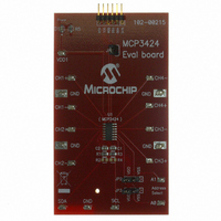
FIGURE 1-1:
Figure 1-1 shows the MCP3424 Evaluation Board, and Figure 1-2 shows the
MCP3424 and PICkit Serial Analyzer.
The following describes how to use them together:
1. Connect the MCP3424 Evaluation Board’s 6-pin socket to the PICkit Serial Ana-
2. Connect the oscilloscope probes to the SCL and SDA test pins (optional).
3. V
4. Address bit selection using JP2 and JP3 connectors.
The I
• MCP3424 I
• A2, A1, A0 Address Bits: determined by the JP2 (Adr1 pin) and JP3 (Adr0 pin)
• The JP2 and JP3 connectors are external address bit selections. Connect these
• See Table 1-1 for the I
5. Connecting V
6. Connecting the analog inputs: If you need to measure a single-ended input,
• Connecting the inputs: The MCP3424 Evaluation Board has input pads for ana-
7. Use the PICkit Serial Analyzer PC GUI to send I
pins to V
log inputs for each input channel. You can connect all inputs at the same time and
multiplex the input channel using configuration register settings. You can also
leave the unused channel inputs floating
lyzer as shown in Figure 1-2.
own external V
(a) Connect JP1, if using V
(b) Disconnect JP1 and apply V
lyzer will provide V
D1 turns on, when you execute the command using the PICkit Serial Analyzer.
connect the unused pin (example, CHX-) to V
2
DD
C device code and address bits of the MCP3424 device are:
Selection: You can use the V
SS
, V
2
C device code: ‘1101’
DD
, float, or connect any arbitrary voltage
DD
DD
Front View of the MCP3424 Evaluation Board.
: LED D1 turns on when V
. The JP1 connector selects the V
DD
2
C Device Address bits and JP2 and JP3 connections
automatically, if it is connected to the PC. Make sure LED
DD
from PICkit Serial Analyzer,
DD
DD
at V
from the PICkit Serial Analyzer or use your
DD
1 pin, if you are using an external V
DD
SS
is applied. The PICkit Serial Ana-
.
2
C write and read commands.
DD
© 2008 Microchip Technology Inc.
path.
DD
.
Related parts for MCP3424EV
Image
Part Number
Description
Manufacturer
Datasheet
Request
R

Part Number:
Description:
Manufacturer:
Microchip Technology Inc.
Datasheet:
Part Number:
Description:
Manufacturer:
Microchip Technology Inc.
Datasheet:
Part Number:
Description:
Manufacturer:
Microchip Technology Inc.
Datasheet:
Part Number:
Description:
Manufacturer:
Microchip Technology Inc.
Datasheet:
Part Number:
Description:
Manufacturer:
Microchip Technology Inc.
Datasheet:
Part Number:
Description:
Manufacturer:
Microchip Technology Inc.
Datasheet:
Part Number:
Description:
Manufacturer:
Microchip Technology Inc.
Datasheet:
Part Number:
Description:
Manufacturer:
Microchip Technology Inc.
Datasheet: