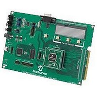
MCP3901EV-MCU16 Microchip Technology, MCP3901EV-MCU16 Datasheet - Page 12

MCP3901EV-MCU16
Manufacturer Part Number
MCP3901EV-MCU16
Description
BOARD EVAL FOR 2CH ADC MCP3901
Manufacturer
Microchip Technology
Datasheets
1.MCP3901A0-ISS.pdf
(60 pages)
2.MCP3901A0-ISS.pdf
(30 pages)
3.MCP3901EV-MCU16.pdf
(38 pages)
4.MCP3901EV-MCU16.pdf
(38 pages)
Specifications of MCP3901EV-MCU16
Number Of Adc's
2
Number Of Bits
24
Data Interface
SPI™
Inputs Per Adc
1 Differential
Input Range
±1 V
Voltage Supply Source
Analog and Digital
Operating Temperature
-40°C ~ 85°C
Utilized Ic / Part
MCP3901
Silicon Manufacturer
Microchip
Application Sub Type
ADC
Kit Application Type
Data Converter
Silicon Core Number
MCP3901, PIC24F, PIC24H, DsPIC33, PIC18F86J55
Kit Contents
Board
Lead Free Status / RoHS Status
Lead free / RoHS Compliant
MCP3901 ADC Evaluation Board for 16-Bit MCUs User’s Guide
1.3
DS51845B-page 12
MCP3901 DELTA-SIGMA SAMPLING/MCLK OPTIONS
The MCP3901 device is an ADC with a second order modulator and a third order sync
filter. This Delta-Sigma A/D converter has an adjustable oversampling ratio. The CLKIN
pin of the MCP3901 is the oversampling clock (MCLK) input. The MCP3901 ADC
Evaluation Board for 16-Bit MCUs offers two different options for the MCP3901 master
clock (MCLK).
1.3.1
The MCP3901 ADC Evaluation Board for 16-Bit MCUs is populated with a 3.58 MHz
crystal, which is used as a clock source by placing jumpers in the following position on
the MCP3901 Digital I/O header block:
FIGURE 1-3:
1.3.2
The PIC MCU can be used to generate the CLKIN (MCLK) signal for the MCP3901,
setting the ADC sample rate through the use of the output compare module OC1. To
use this, make the following jumper change to the MCP3901 Digital I/O header block:
FIGURE 1-4:
The frequency of the OC1 output is based on the PR1 bits settings in the firmware
(for both PIC24 and dsPIC33 PIM modules supplied with this system). The signal
frequency from OC1 can be changed by the user from the PS software by changing the
value in the sampling rate control box. A low number will generate a high frequency sig-
nal. The value of the sampling rate, which is directly proportional with the clock
frequency from OC1, is indicated in the sampling speed indicator box in the PC
software (see Figure 3-1).
Using the Crystal X2
Driving the Clock with the PIM Module
ADC Clock Selection Jumpers – External Crystal.
ADC Clock Selection Jumpers – Clock from MCU.
CLKOUT
CLKOUT
CLKIN
CLKIN
CLKIN
CLKIN
XTAL
XTAL
XTAL
XTAL
PIM OC1
PIM OC1
2010 Microchip Technology Inc.


