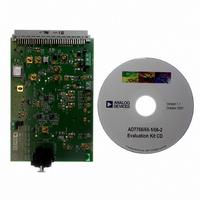
EVAL-AD7766-1EDZ Analog Devices Inc, EVAL-AD7766-1EDZ Datasheet - Page 15

EVAL-AD7766-1EDZ
Manufacturer Part Number
EVAL-AD7766-1EDZ
Description
BOARD EVAL AD7766-1 64KSPS 111DB
Manufacturer
Analog Devices Inc
Specifications of EVAL-AD7766-1EDZ
Number Of Adc's
1
Number Of Bits
24
Sampling Rate (per Second)
64k
Data Interface
Serial
Inputs Per Adc
1 Differential
Input Range
±VREF
Power (typ) @ Conditions
10.5mW @ 64kSPS
Voltage Supply Source
Analog and Digital
Operating Temperature
-40°C ~ 105°C
Utilized Ic / Part
AD7766-1
Lead Free Status / RoHS Status
Lead free / RoHS Compliant
THEORY OF OPERATION
The AD7766/AD7766-1/AD7766-2 operate using a fully
differential analog input applied to a successive approximation
(SAR) core. The output of the oversampled SAR is filtered using
a linear-phase digital FIR filter. The fully filtered data is output
in a serial format, with the MSB being clocked out first.
AD7766/AD7766-1/AD7766-2 TRANSFER
FUNCTION
The conversion results of the AD7766/AD7766-1/AD7766-2
are output in a twos complement, 24-bit serial format. The fully
differential inputs V
AD7766-1/AD7766-2 relative to the reference voltage input
(V
CONVERTER OPERATION
Internally, the input waveform applied to the SAR core is
converted and an equivalent digital word is output to the digital
filter at a rate equal to MCLK. By employing oversampling, the
quantization noise of the converter is spread across a wide
bandwidth from 0 to f
contained in the signal band of interest is reduced (see
Figure 29).
COMPLEMENT
REF+
011 ... 111
011 ... 110
000 ... 010
000 ... 001
000 ... 000
111 ... 111
111 ... 110
100 ... 001
100 ... 000
24 BITS
TWOS
) as shown in Figure 28.
BAND OF INTEREST
BAND OF INTEREST
V
Figure 28. AD7766/AD7766-1/AD7766-2 Transfer Function
IN–
= V
V
IN+
REF+
Figure 30. Digital Filter Cutoff Frequency
= 0V
– 1LSB
Figure 29. Quantization Noise
IN+
DIGITAL FILTER CUTOFF FREQUENCY
MCLK
QUANTIZATION NOISE
and V
. This means that the noise energy
V
V
IN−
IN+
IN–
are scaled by the AD7766/
=
=
V
V
REF+
REF+
2
2
V
IN+
= V
V
f
f
MCLK/2
MCLK/2
IN–
REF+
= 0V
– 1LSB
Rev. C | Page 15 of 24
The digital filtering that follows the converter output acts to
remove the out-of-band quantization noise (see Figure 30). This
also has the effect of reducing the data rate from f
input of the filter to f
output, depending on which model of the device is being used.
The digital filter consists of three separate filter blocks. Figure 31
shows the three constituent blocks of the filter. The order of
decimation of the first filter block is set as 2, 4, or 8. The
remaining sections each operate with a decimation of 2.
Table 6 shows the three available models of the AD7766, listing
the change in output data rate relative to the order of decimation
rate implemented. This brings into focus the trade-off that exists
between extra filtering and reduction in bandwidth, whereby
using a filter option with a larger decimation rate increases the
noise performance while decreasing the usable input bandwidth.
Table 6. AD7766 Models
Model
AD7766
AD7766-1
AD7766-2
Note that the output data rates shown in Table 6 are realized
when using the maximum MCLK input frequency of 1.024 MHz.
The output data rate scales linearly with the MCLK frequency,
as does the digital power dissipated in the device.
The settling time of the filter implemented on the AD7766,
AD7766-1, and AD7766-2 is related to the length of the filter
employed. The response of the filter in the time domain sets the
filter settling time. Table 7 shows the filter settling times of the
AD7766/AD7766-1/AD7766-2.
The frequency responses of the digital filters on the AD7766,
AD7766-1, and AD7766-2 are shown in Figure 32, Figure 33,
and Figure 34, respectively. At the Nyquist frequency (output
data rate/2), the digital filter provides 6 dB of attenuation. In each
case, the filter provides stop-band attenuation of 100 dB and
pass-band ripple of ±0.005 dB.
STREAM
DATA
(n = 1 for AD7766, n = 2 for AD7766-1, n = 4 for AD7766-2)
Decimation Rate
8
16
32
DEC × (2 × n)
SINC FILTER
STAGE 1
MCLK
Figure 31. FIR Filter Stages
/8, f
DIGITAL FILTER
MCLK
FIR FILTER
STAGE 2
DEC × 2
/16, or f
Output Data Rate (ODR)
128 kHz
64 kHz
32 kHz
MCLK
/32 at the digital
FIR FILTER
STAGE 3
DEC × 2
MCLK
AD7766
at the
SDO


